
The voltage drop formula is ΔV = I × R when R represents the complete resistive current path. Using resistance per unit length instead, the common approximations are ΔV = 2IrL for a single-phase circuit and ΔV = √3IrL for a balanced three-phase circuit. Here, L is the one-way distance from source to load.
Those compact formulas assume a resistance-dominated circuit and approximately unity power factor. They are useful starting points, not complete conductor-selection rules. An accurate calculation also identifies the voltage reference, conductor temperature, load condition and whether reactance matters.
Choose the voltage drop formula that matches the circuit
| Model | Formula | Meaning of resistance and result |
|---|---|---|
| Complete resistive path | ΔV = I × Rpath | Rpath already includes every relevant series conductor. |
| Single-phase, equal outgoing and return conductors | ΔV ≈ 2 × I × r × L | r is one conductor’s resistance per unit length; L is one-way distance. |
| Balanced three-phase | ΔVLL ≈ √3 × I × r × L | I is line current; the result is the approximate line-to-line drop. |
| Percentage drop | ΔV% = 100 × ΔV / Vsource | The source voltage must use the same reference as the calculated drop. |
In these equations, ΔV is in volts, I is in amperes and resistance is in ohms. The product rL must resolve to ohms. For resistance quoted in Ω/1,000 ft, multiply by L in feet and divide by 1,000. For Ω/km, use kilometers instead. A feet-to-kilometers mismatch can dominate every other refinement.
One-way length is not loop length
A simple single-phase circuit has an outgoing path and a return path. If each path is 100 ft long, L remains 100 ft in the 2IrL expression. The factor 2 accounts for both conductors. Entering 200 ft and retaining that factor counts the return path twice.
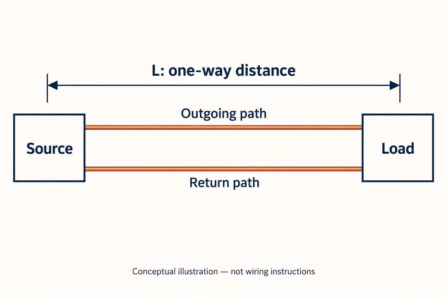
If a table or calculation has already supplied complete loop resistance, use IRpath directly. Before choosing a formula, write down whether the resistance value describes one conductor, a complete loop or a per-length quantity. This small notation check prevents a plausible-looking result from being wrong by a factor of two.
Single-phase worked example: 120 V over a 100 ft route
Consider a hypothetical resistance-only circuit with a 120 V source, a 20 A steady load and a 100 ft one-way route. Assume each conductor has a resistance of 2.0 Ω/1,000 ft at the operating condition being modeled. This resistance is an example input, not a recommended wire size.
- One conductor’s resistance: 2.0 × 100 / 1,000 = 0.20 Ω.
- Complete outgoing-and-return resistance: 2 × 0.20 = 0.40 Ω.
- Voltage drop: 20 × 0.40 = 8.0 V.
- Percentage drop: 100 × 8.0 / 120 = 6.67%.
- Approximate voltage at the load: 120 − 8.0 = 112 V.
The direct expression gives the same answer: 2 × 20 × 2.0 × 100 / 1,000 = 8.0 V. Showing both routes is useful because they expose the meaning of each input. One calculation builds the loop explicitly; the other includes that loop through the factor 2.
The result does not establish that 112 V is acceptable for a particular machine. That decision requires the equipment’s permitted input range and the applicable project requirements. It also does not prove the conductor can safely carry 20 A: voltage drop and current-carrying capacity are separate design checks.
This example treats current as fixed. If the actual load changes its current as terminal voltage changes, the designer needs an appropriate load model. A calculation built around one operating point should not be presented as a prediction for every operating condition.
Three-phase worked example: use line-to-line voltage consistently
Now assume a balanced three-phase load supplied at 208 V line-to-line. Line current is 30 A, one-way distance is 100 ft and each phase conductor has an assumed resistance of 1.0 Ω/1,000 ft. Power factor is approximately one, and reactance is neglected.
- One phase conductor’s resistance: 1.0 × 100 / 1,000 = 0.10 Ω.
- Approximate line-to-line drop: √3 × 30 × 0.10 = 5.196 V.
- Percentage drop: 100 × 5.196 / 208 = 2.50%, rounded.
- Approximate load voltage: 208 − 5.196 = 202.8 V line-to-line.
There is no additional factor 2 in this expression. The √3 factor reflects the balanced three-phase relationship; it is not a shorthand instruction to add another return conductor. Applying both factors would mix two different circuit models.
The denominator is 208 V because the calculated drop is line-to-line. Dividing that result by a 120 V line-to-neutral value would combine incompatible references. A worksheet should label voltage as L-L or L-N rather than leaving an unqualified “V” beside a number.
A single-phase branch supplied from a three-phase distribution system still needs the model appropriate to that branch. The building’s service label alone does not determine which formula describes an individual load. Likewise, the balanced formula should not be assumed to describe an unbalanced neutral-bearing circuit without further analysis.
When the simple resistance formula needs an AC correction
In AC circuits, conductor impedance can include both resistance R and reactance X. For a steady lagging load, a common approximate drop model uses the term R cosφ + X sinφ, where cosφ is the load power factor. The resistive-only expression is a simplified case, not a competing physical principle.
Using R and X per unit length, the approximate single-phase expression is 2IL(R cosφ + X sinφ). For a balanced three-phase circuit, the multiplier becomes √3. L must use the same distance unit as the per-length impedance values. These steady-load expressions do not, by themselves, model starting transients or harmonic behavior.
Published resistance constants also carry assumptions. A value based on one conductor material or temperature cannot automatically represent another. For practical calculations, a documented manufacturer or recognized engineering data source is more useful than a remembered constant with no units or temperature attached.
Audit the inputs before trusting a calculator
A calculator can process an incorrect circuit description perfectly. The person preparing the calculation should therefore record inputs separately before reading the output. The Southwire calculator, for example, asks for phase, conductor and operating inputs rather than treating route length as the only variable.
- Circuit model: single-phase branch or balanced three-phase load, not merely the building service.
- Voltage reference: the actual source value and whether it is line-to-line or line-to-neutral.
- Load condition: steady current and power factor for the operating point under review.
- Conductor data: material, size, resistance or impedance source, and temperature basis.
- Route length: one-way distance, with the tool’s own definition checked.
- Output meaning: volts, percentage, estimated terminal voltage, or a conductor-selection result.
When two tools disagree, compare their assumptions before averaging their results. One may use AC impedance while another uses DC resistance. They may also model different temperatures or interpret the entered distance differently. A more precise decimal output does not resolve a different physical model.
Use sensitivity checks to find what actually changes the result
For the simple resistive model, drop varies directly with current, length and resistance. This makes a sensitivity check quick: change one input, hold the others fixed and recalculate. The check reveals whether the proposed change addresses the modeled cause rather than an unrelated symptom.
| Change to the single-phase example | Calculated drop | What stayed fixed |
|---|---|---|
| Original: 20 A, 100 ft, 2.0 Ω/1,000 ft | 8.0 V | 120 V source; resistance-only model |
| Half the route length: 50 ft | 4.0 V | Current and resistance per length |
| Half the current: 10 A | 4.0 V | Route length and resistance per length |
| Half the resistance: 1.0 Ω/1,000 ft | 4.0 V | Route length and current |
| Double the route length: 200 ft | 16.0 V | Current and resistance per length |
These are mathematical comparisons, not construction recommendations. Changing conductor size, route or equipment supply involves constraints outside this table. The useful conclusion is narrower: the calculation identifies which variable must change to reduce the modeled conductor drop.
Keep a calculation record another person can reproduce
A useful project record contains the circuit identifier, source voltage reference, load current, power factor, one-way length and conductor data source. It states the temperature basis and whether reactance was included. It then shows the formula, substitutions, unrounded result and final rounded result.
The record should also state the decision still outstanding. For example: “Calculated steady-load drop only; equipment input tolerance and conductor suitability require separate verification.” This is more informative than marking a result “pass” without naming the criterion. It lets the equipment supplier, designer and purchaser discuss the same operating condition.
Retaining the original inputs matters when a layout changes. A longer route or a revised load can invalidate an earlier result even though the spreadsheet formula has not changed. Revision control belongs to the circuit description as well as the final percentage.
A percentage can change without changing the conductor drop
Percentage is a ratio, so the denominator deserves its own check. Suppose the original resistance-only example retained the same 20 A current, 100 ft route and conductor resistance, but the hypothetical source were 240 V. The calculated conductor drop would remain 8 V. Its percentage would become 100 × 8 / 240 = 3.33%.
That arithmetic does not recommend changing the supply voltage. It demonstrates why the voltage reference must be recorded alongside a percentage. An 8 V drop and a 3.33% drop describe different quantities; one cannot be substituted for the other without the source voltage.
If the comparison instead holds electrical input power constant, current must be recalculated for the revised voltage and power factor. The earlier fixed-current example no longer applies unchanged. This distinction helps reviewers spot calculations that quietly switch between equal-current and equal-power assumptions.
A surge protective device does not correct steady voltage drop
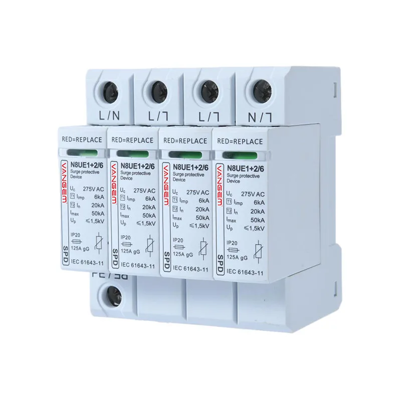
Conductor voltage drop and transient overvoltage are different problems. A surge protective device addresses short-duration overvoltage events; it does not raise a continuously low load voltage or remove conductor resistance. An SPD should therefore not be proposed as the fix for the 8 V drop calculated above.
Where transient protection is a separate project requirement, the AC surge protection device category provides the relevant product pathway. Selection still depends on the actual supply configuration and the specific manufacturer’s documentation, not the voltage-drop percentage.
The practical sequence is to calculate the steady-load condition with consistent units, verify the equipment’s supply requirements, and evaluate transient protection separately. One correct formula can answer the voltage-drop question; it cannot replace the other design decisions.
DC voltage drop: use the complete outgoing-and-return path
For a simple two-wire DC circuit with equal conductor resistance, the resistance-only expression is also ΔV = 2IrL, where L is one-way length and r is one conductor’s resistance per unit length. The physical point is the complete current path, not whether the supply label says AC or DC. If the return path differs, add the actual outgoing and return resistances instead of assuming they are equal.
Consider a hypothetical 48 V DC circuit carrying 10 A over a 20 m one-way route. Assume each conductor has resistance of 0.005 Ω/m at the modeled operating condition. The complete path resistance is 2 × 20 × 0.005 = 0.20 Ω. The drop is 10 × 0.20 = 2.0 V, or 100 × 2 / 48 = 4.17%. The estimated load voltage is 46 V.
The assumed resistance is not a cable-size recommendation. A PV array also needs its actual voltage/current behavior, temperature conditions and circuit configuration considered; the fixed-current example is not a PV design calculation.
Voltage drop calculation mistakes to check first
| Mistake | Effect on the calculation | Correction |
|---|---|---|
| Using loop length in 2IrL | Counts the return path twice. | Use one-way L, or use complete path resistance with IR directly. |
| Mixing Ω/km and metres | Introduces a factor-of-1000 error. | Convert distance to kilometres, or resistance to Ω/m. |
| Using L-N voltage for an L-L result | Produces an inconsistent percentage. | Keep the result and denominator on the same voltage reference. |
| Treating resistance as a fixed universal constant | Can hide material and temperature assumptions. | Record the conductor-data source and operating basis. |
| Applying a steady-load result to motor starting | Uses the wrong operating current and possibly the wrong power factor. | Model the relevant operating condition separately. |
Formula, calculator and measured voltage: what each tells you
A formula shows the relationship between inputs. A calculator applies its chosen model and data tables. A voltage measurement describes the system at the time and location of the measurement. They can disagree because the input current, source condition, temperature or model differs; the disagreement does not automatically identify which conductor or device needs replacement.
For a reproducible comparison, retain the input sheet, formula, units, result and calculator settings. The Southwire tool listed in References is an external calculation resource with its own application scope. This article provides worked examples; it does not claim to contain an interactive calculator or to approve conductor sizes.