

The central difference in solar panel series vs parallel comparisons is voltage and current. With matched modules under the same conditions, series groups add voltage while current remains that of one module. Parallel groups add current while voltage remains that of one module. Neither arrangement creates extra rated panel power.
The appropriate comparison includes the receiving inverter or charge controller, not just the panels. Operating voltage, open-circuit voltage and current describe different conditions. Keeping them separate makes a specification easier to understand without turning a general comparison into a wiring recommendation.
Solar panel series vs parallel: the same four modules
Consider four identical, hypothetical modules at the same reference conditions. Each has a maximum-power voltage, Vmp, of 40 V and maximum-power current, Imp, of 10 A. The ideal maximum power per module is therefore 40 V × 10 A = 400 W.
For this example, each module also has an open-circuit voltage, Voc, of 48 V and a short-circuit current, Isc, of 10.5 A. These are separate operating conditions, not another voltage/current pair for calculating delivered power. The figures are assumptions for the comparison, not specifications of a Wanze product.
| Arrangement | Vmp | Imp | Ideal power at MPP | Voc | Isc |
|---|---|---|---|---|---|
| 4S: four modules in series | 160 V | 10 A | 1,600 W | 192 V | 10.5 A |
| 4P: four modules in parallel | 40 V | 40 A | 1,600 W | 48 V | 42 A |
| 2S2P: two equal series pairs in parallel | 80 V | 20 A | 1,600 W | 96 V | 21 A |
The maximum-power calculation is consistent across the three rows: 160 × 10, 40 × 40 and 80 × 20 each equal 1,600 W. There are still only four hypothetical 400 W modules. Changing their grouping changes the voltage/current combination, not the sum of their ratings.
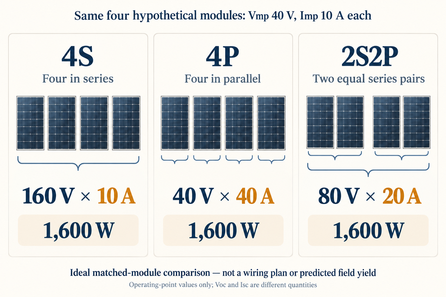
The table deliberately includes Voc and Isc in separate columns. For example, 192 V is the series group’s open-circuit value at the assumed reference conditions. It is not the 160 V operating value, and it is not a cold-temperature-corrected project limit.
Victron’s solar-array explanation supports the underlying distinction: series increases voltage, parallel increases current, and total array power reflects the module ratings. The worked values here are original arithmetic rather than a reproduction of the manufacturer’s example.
What changes in series, parallel and mixed groups?
A series group presents the combined module voltages at a common current. In the ideal matched-module example, four 40 V operating contributions give 160 V at 10 A. The corresponding open-circuit contributions add separately: four assumed 48 V values give 192 V.
A parallel group presents combined branch currents at a common voltage. Four assumed 10 A operating contributions give 40 A at 40 V. The separate short-circuit comparison gives four times 10.5 A, or 42 A. Mixing an operating current with an open-circuit voltage would describe neither condition correctly.
A series-parallel group applies both relationships. In the 2S2P example, each equal pair contributes an operating voltage of 80 V at 10 A. Comparing two such pairs in parallel gives 80 V at 20 A. This explains the notation without specifying any physical connector or terminal arrangement.
When comparing solar panels in series vs parallel, the proposal should identify module models, exposure conditions and the receiving input. “Higher voltage” alone leaves the quantity undefined: the buyer still needs to distinguish maximum-power operation from open circuit.
Operating values and equipment limits are different records
Vmp and Imp describe the voltage and current at the maximum-power point under stated conditions. Voc describes voltage at open circuit, while Isc describes current at short circuit. Voc and Isc are not simultaneously available as an operating voltage/current pair.
That distinction explains why multiplying Voc by Isc does not give the module’s maximum delivered power. In the hypothetical module, 40 V × 10 A is the defined maximum-power calculation. The separate 48 V and 10.5 A assumptions belong to different endpoints of the electrical characteristic.
The receiving equipment introduces another set of quantities. An inverter or solar charge controller has its own documented input limits. An array’s operating-point calculation cannot, by itself, establish that those limits are met. The proposed arrangement and the receiving input need to be described in the same record.
SMA’s published PV-input requirements provide a concrete example of why model documents matter. They distinguish input voltage and current constraints and refer specifically to cold-condition open-circuit voltage. Those are requirements for the identified equipment, not a universal string-length rule for all inverters.
| Information | What it describes | What cannot replace it |
|---|---|---|
| Module Vmp and Imp | Maximum-power operation at stated conditions | Voc and Isc multiplied together |
| Module Voc and temperature information | The basis for assessing open-circuit voltage conditions | An operating-voltage value alone |
| Module Isc | A distinct short-circuit-current characteristic | A maximum-power-current label used without distinction |
| Receiver model and input limits | The specific destination for the proposed array | A generic “solar inverter” description |
| Input grouping and module identity | Which modules belong to which receiving input | Total panel count without grouping |
For a purchasing comparison, the missing item should remain visible. If a proposal supplies only total watts and panel count, voltage/current compatibility is still unresolved. Filling that gap requires the actual module and receiver documentation, not another simplified example with more favorable numbers.
Shading does not have one universal winner
The series-versus-parallel label alone cannot predict a shaded array’s output. Module exposure and the conversion architecture also matter. DOE distinguishes string-level conversion from module-level microinverters and explains that shading can affect the amount of power available from a string.
This makes “parallel is always better in shade” too broad for a procurement specification. It leaves out the actual equipment and the way modules are grouped. A useful comparison describes the exposure problem and the proposed conversion arrangement rather than assigning a universal benefit to one word.
A quantified performance comparison needs the module characteristics, exposure assumptions and receiving conversion equipment for both alternatives. If the converter changes along with the grouping, a measured output difference cannot be attributed to series versus parallel alone. The supplier’s assessment should identify which inputs are held constant and which are different, rather than promise a universal shading improvement.
PV surge protection does not resolve an array mismatch
A PV surge protective device addresses transient overvoltage. It does not alter the module grouping, control the maximum-power operating point or increase the module ratings. Schneider Electric’s SPD definition concerns short-duration voltage transients, a different phenomenon from the normal operating quantities compared above.
Wanze’s solar PV surge protection device category is a relevant pathway when the separately documented question concerns PV-side transient protection. It is not an alternative to resolving an incompatible array or an incomplete receiving-equipment specification.
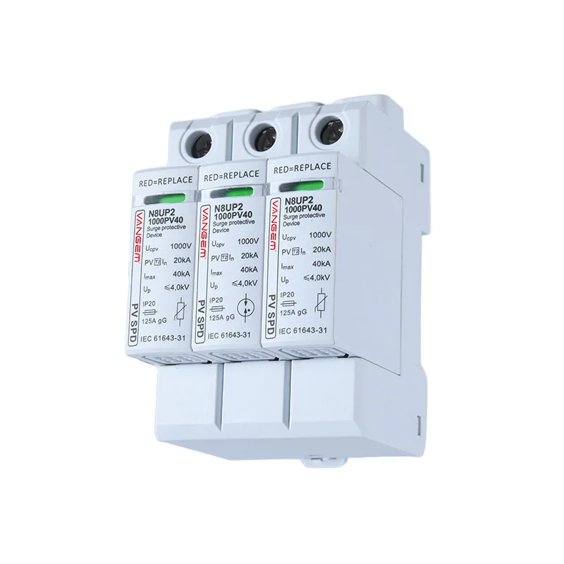
For a PV transient-protection enquiry, provide the verified module grouping, array electrical characteristics, receiving equipment model and the circuit being reviewed. These records define the question for the supplier; the hypothetical comparison above does not establish a protective-device selection.
References
- Victron Energy: Wiring Unlimited, solar-array fundamentals — series/parallel relationships, not installation procedures.
- SMA: PV module requirements for the specified US inverter inputs
- US Department of Energy: Inverters and Grid Services Basics
- Schneider Electric: What is an SPD?