

A latching relay keeps its selected contact position after the coil input ends. Another suitable input changes that position. This retained state distinguishes a latching, or bistable, relay from a conventional non-latching relay that returns when its coil loses power.
The distinction concerns the relay’s contacts. It does not mean the connected load has its own power source, or that a machine will resume operation after an outage. Understanding the holding mechanism and the reset arrangement answers different parts of the question.
What does a latching relay keep after the input ends?
The relay retains a contact position, rather than a continuing command. A set input establishes one state; the appropriate reset input establishes the other. Continuous coil excitation is not needed simply to preserve the selected state.
The word “latching” describes the retained behavior. The particular relay’s operating description identifies how its set and reset inputs establish that state. A brief feature label does not identify the coil arrangement or the external control circuit.
Three things are worth keeping separate when reading a description: the input applied to the coil, the resulting contact position, and the supply available to the load. A statement about one does not establish the other two.
For example, “the contact stays set without coil power” describes memory in the relay. Rewriting it as “the equipment stays powered” adds a claim about the load circuit that the original sentence never made. The manufacturer’s contact-state description is useful precisely because its scope is narrow.
Single-coil and dual-coil latching relay reset methods
Single-coil and dual-coil descriptions identify how the set and reset inputs are arranged. They do not identify the number of switched contacts. Coil configuration and contact configuration need separate entries in a technical comparison.
The following distinction follows the operating forms in Panasonic’s relay terminology guide:
| Coil arrangement | Set/reset distinction | What the label leaves unspecified |
|---|---|---|
| Single-coil latching relay | One winding; the described reset input has the opposite polarity to the set input. | The exact model’s terminals and permitted input conditions. |
| Dual-coil latching relay | Separate set and reset windings establish the two states. | The exact model’s connection details and permitted input conditions. |
This is a classification of operating descriptions, not a drive circuit. A generic “single-coil” label cannot supply a pinout or pulse specification. Those details belong to the applicable model documentation.
A buyer comparing two parts can therefore resolve the coil type before considering a replacement. Matching the word “latching” establishes a shared general behavior; it does not establish that the control interface or contact arrangement matches. Where the description is incomplete, the unresolved field should remain explicit rather than being filled from a similar-looking part.
A retained contact is different from a powered load
A contact can retain its position without providing energy to the load. Relay memory and load supply are separate concepts, even when both appear in the same equipment description.
Consider a conceptual sequence: the relay receives a valid set input, the input ends, and the contact remains in its set state. A later valid reset input changes the contact state. The illustration below follows that sequence without specifying an actual coil waveform or terminal connection.
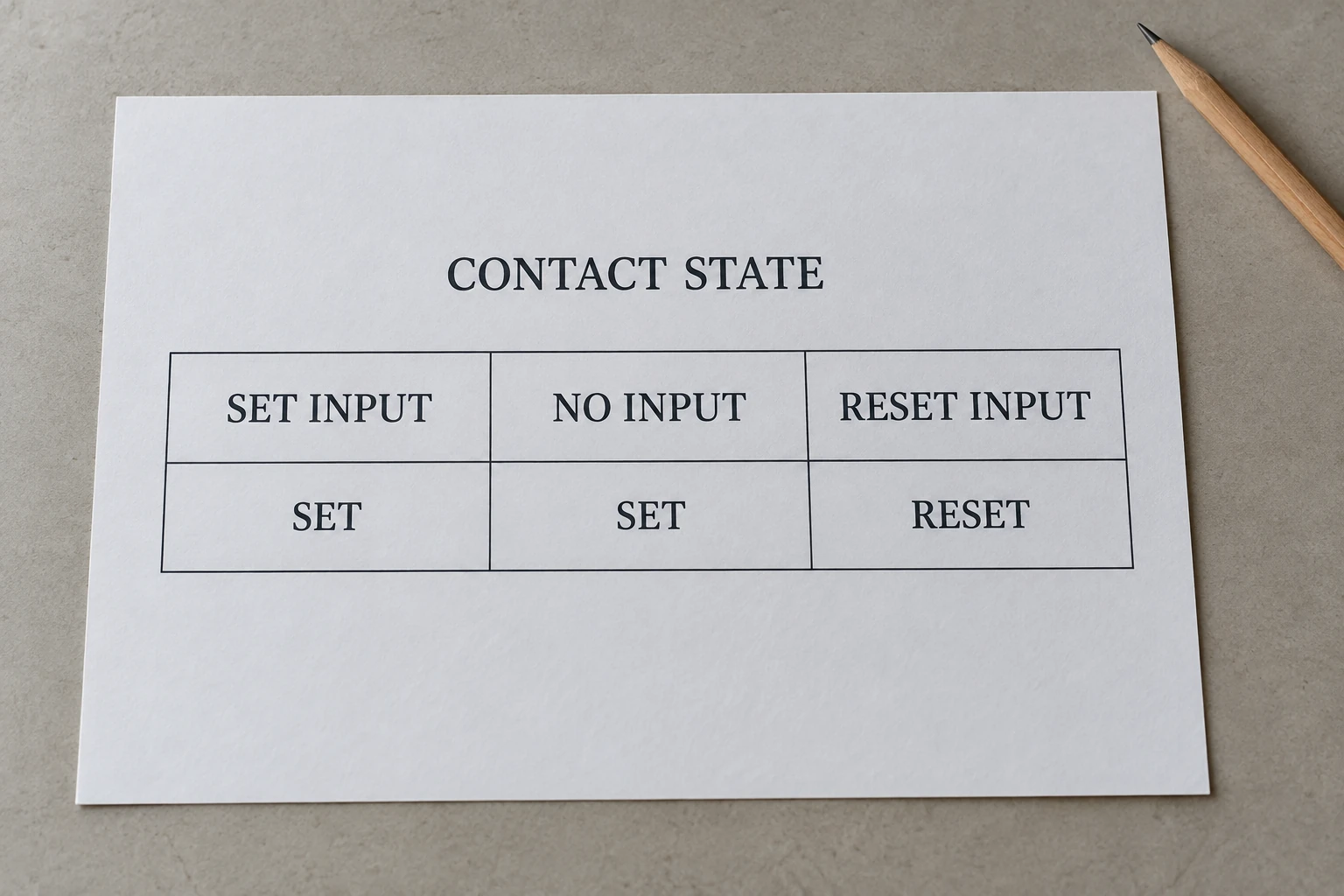
The middle column is the important one: the input has ended, while the contact state remains. It does not show a running motor, an energized output or a system restart. Those conclusions require the equipment-level control description.
Likewise, a coil-power saving claim should stay on the coil side. The source of power for the controlled load remains a separate question. A component description cannot establish the energy use of an entire installation.
Latching relay vs a self-holding circuit
A self-holding circuit can maintain operation after the initiating command disappears while continuing to energize a conventional coil. A latching relay retains its contact state after coil excitation itself ends. Removing the command and removing coil power are different events.
The manufacturer’s operating forms distinguish monostable relays, which return when coil power is removed, from bistable relays, which retain their switched position. Mitsubishi Electric’s motor-starter FAQ describes self-holding through an auxiliary contact that maintains coil excitation after the ON command disappears. In that described circuit, an OFF operation or power outage cancels the holding state.
| Question | Latching relay | Described self-holding circuit |
|---|---|---|
| What preserves the state? | The relay’s latching mechanism. | A circuit that continues coil excitation. |
| What happens after the initiating command ends? | The selected contact state remains. | The maintained coil supply can preserve the operated state. |
| What if coil excitation ends? | The retained contact position remains. | The conventional coil no longer has its holding excitation. |
| What document resolves the behavior? | The relay’s operating description. | The equipment’s control-circuit description. |
The comparison explains why “stays on after a short command” is an incomplete specification. Both descriptions can fit that phrase while depending on different holding mechanisms. The missing question is whether coil excitation also ends.
This comparison does not classify every controller memory function. A software latch or an equipment-level retained command needs its own description; its name cannot be used to infer the relay hardware inside it.
How to read a relay description without assuming its behavior
A useful description identifies the retained state, coil arrangement and reset method separately. It also distinguishes relay behavior from the behavior of the equipment using it.
Suppose a quotation says only “pulse-operated relay, retained output.” That wording leaves several possibilities unresolved. The accompanying documentation should establish whether retention belongs to a bistable component or to a surrounding control circuit.
A focused comparison can ask for:
- Operating form: latching/bistable or non-latching/monostable, using the manufacturer’s terminology.
- Coil arrangement: the documented set/reset arrangement for the exact model.
- Contact description: the switched positions and contact arrangement, recorded separately from coil count.
- System behavior: a separate explanation of what the equipment does after loss and restoration of its supplies.
These questions improve the description without prescribing a test or an electrical connection. An answer about retained contact position can close the relay-memory question while leaving equipment restart unresolved. Keeping those answers separate makes a comparison more precise.
Keep control-state memory separate from surge protection
State retention describes switching behavior. Transient-overvoltage protection is a separate component function and needs its own documentation.
Wanze’s AC surge protection devices category addresses that surge-protection role. It provides a separate product-research path, rather than evidence for a relay’s set/reset behavior.
The practical reading rule is to ask what is being retained and what supply has disappeared. Once those two facts are clear, single-coil, dual-coil and self-holding descriptions become easier to compare without treating them as interchangeable equipment functions.