

A single inline package, or SIP, places its external leads in one row. The name describes the lead arrangement, not the circuit inside. Two components can have a similar narrow outline and the same pin count while connecting those pins differently.
For identification or purchasing, keep three questions separate: what is the mechanical package, what does each terminal do, and which complete manufacturer order code specifies the required part? A photograph can help identify the package family. The datasheet resolves the details needed to distinguish one device from another.
Recognize the single inline package before reading its function
The visible clue is a single line of leads emerging from the package. Traditional examples include upright resistor-network bodies with leads intended for a row of board holes. That familiar appearance does not establish a universal body size, lead spacing or mounting requirement.
The Bourns 4600X datasheet provides a concrete example. Its mechanical drawing shows a one-row package and a pin-one reference. Separate fields identify the pin count, physical configuration and electrical configuration. Reading only the outline therefore leaves part of the device identity unresolved.
Start with the full manufacturer reference when one is available. A package nickname such as “SIP resistor” may identify the broad component type, but it does not select a particular internal network, resistance option or termination suffix.
SIP and System in Package answer different questions
Single inline package describes external lead geometry. System in Package, often written SiP, describes functional integration within a package. Amkor’s SiP documentation describes multi-component, multi-function products, which is a different concept from arranging external leads in one row.
Capitalization is a useful clue, but it should not carry the entire meaning in a quotation or parts list. Write the expanded term and include the manufacturer reference and drawing. A request for “SIP packaging” alone can otherwise leave the supplier unsure whether the discussion concerns a lead arrangement or an integration technology.
Neither abbreviation supplies a complete pinout. For a finished component, the applicable manufacturer documentation still needs to identify the connections and package drawing.
The same outline can contain a different resistor circuit
A resistor network illustrates why the internal diagram matters. Within the Bourns 4600X family, the ordering information identifies electrical configuration 101 as bussed and 102 as isolated. These are family-specific configuration codes, not universal suffix rules for every SIP manufacturer.
In the documented bussed circuit, resistor elements connect between a common bus at pin one and separate terminals. In the isolated circuit, each resistor connects between its own pair of terminals. The package description alone does not tell a buyer which arrangement has been selected.
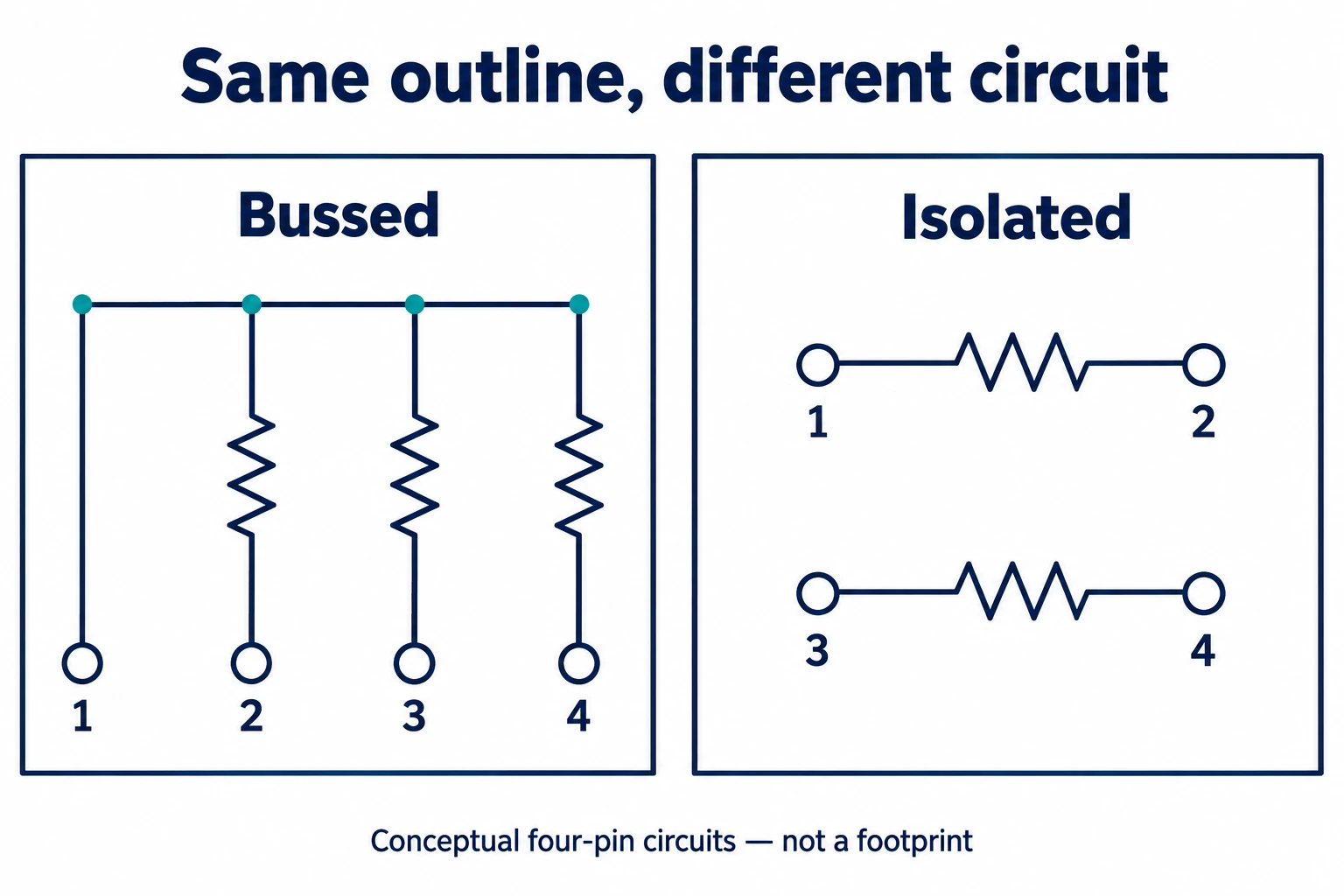
In the illustrated bussed example, pin one is the shared connection for three resistor branches ending at pins two, three and four. The isolated example instead has one resistor between pins one and two, and another between pins three and four. Their connections are different even though both examples have four terminals.
A supplier offering the same pin count and nominal resistance has not yet demonstrated electrical equivalence. The reviewer also needs the network diagram and the other requirements applicable to the design. A common-terminal assumption is particularly easy to miss when the package image looks familiar.
Read the drawing, circuit and order code as separate evidence
A focused datasheet review can keep physical fit and electrical function from being mixed together. The following table is an original reading aid; it does not prescribe dimensions or approve a substitute.
| Document field | What it answers | What it does not establish alone |
|---|---|---|
| Mechanical package drawing | Lead arrangement, body envelope and stated dimensions | The function of every connection |
| Pin-one reference and drawing view | How the document identifies the first terminal and orientation | An orientation inferred only from an unmarked photograph |
| Internal circuit or pin-function diagram | Which terminals share a connection and how the network is arranged | Physical fit or every applicable rating |
| Complete ordering information | The selected pin-count, circuit and other available order options | Equivalence to another manufacturer’s similarly named part |
| Applicable electrical specification | The stated characteristics and their conditions for that part | A universal rating for all single inline packages |
Use the manufacturer’s stated view when interpreting a drawing. Pin-one identification and the numbering convention need to agree with the circuit diagram and the intended documentation. Do not silently convert a package photograph into a layout view.
For a resistor network, review the configuration before interpreting the remaining code. The Bourns ordering example separates pin count from the electrical configuration and resistance-code fields. A short body marking may help locate the relevant document, but the complete order information is the better reference for a purchasing decision.
Where a dimension or electrical condition is missing, record it as an open question. Filling a gap with the value from another visually similar SIP creates an assumption rather than a verified match.
What a clear component handover includes
A useful handover identifies the manufacturer, complete part reference, applicable datasheet revision, package drawing and circuit configuration. If another component is being proposed, keep its information alongside the original reference so that the differences remain visible.
The person reviewing the change should be able to see which evidence supports physical fit and which supports electrical function. A description such as “same SIP package” answers neither question fully. The unresolved fields need a response from the responsible supplier or design owner before the proposed equivalence is accepted.
For this task, the practical output is a complete component identity with explicit unknowns. The single row of leads is the starting point; the drawing, circuit and order code finish the identification.
References
Bourns 4600X Series: Thick Film Conformal SIPs — mechanical drawing, ordering fields and bussed/isolated network diagrams.
Amkor: System in Package data sheet — the separate functional-integration meaning of SiP.