

In a common ball-to-stitch wire-bonding sequence, a stitch bond is the second attachment that completes the wire connection. The first bond attaches one end of the wire, the wire forms a loop, and the stitch attaches the other end to another bonding surface.
That answers the basic question, “What is a stitch bond in chip packaging?” The important qualification is the process context. The name identifies a bond in a described arrangement; it does not, by itself, identify every tool, wire material or package construction.
What is a stitch bond in chip packaging?
In the illustrated forward arrangement, a ball bond sits on a die pad and the wire loop reaches a leadframe pad. The flattened second attachment is the stitch bond. The drawing shows one common arrangement rather than a mandatory direction for all packages.
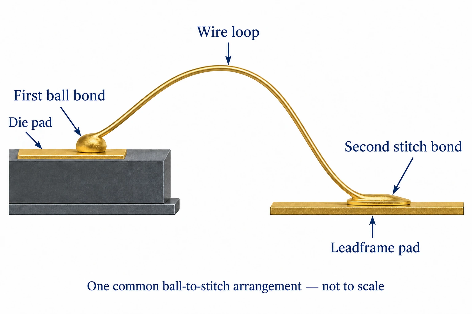
Palomar’s gold-ball-bonding description explains a first ball formed at a capillary, followed by a controlled loop and a second bond often called the stitch. This is the sequence being described here. The wire and its two attachments together form the interconnection.
Read “first” and “second” as sequence terms. They help locate the connection under discussion, but they are not quality grades. A photograph showing two attached ends also cannot establish the process history or acceptance result for that connection.
Ball bond, stitch bond and wedge bonding are not identical labels
A ball-to-stitch connection can be formed using a capillary. Calling the second attachment a stitch therefore does not mean that the entire connection was made with a wedge tool. Tool names and bond names need to be read within the description of the process.
You may also encounter stitch terminology in research on ultrasonic wedge bonding. A 2026 study of bonding to copper leadframes uses that context. Its experimental arrangement is different from simply identifying the second attachment in the capillary-based sequence above.
When two documents appear to disagree, look for that context before concluding that one uses the wrong word. Check the tool, starting arrangement, wire and receiving surface. A short glossary label may leave details that the original process description makes explicit.
| Term in a document | Question it helps answer | What still needs context |
|---|---|---|
| First ball bond | Where does the described sequence begin? | Wire, pad and process arrangement |
| Second stitch bond | Where is the second attachment? | Receiving surface and actual formation process |
| Capillary or wedge tool | Which tool/process context is described? | Connection geometry and evaluation evidence |
Why a stitch-bond claim needs evidence
The name alone does not establish bond strength or reliability. Surface condition, material pairing and process context matter. The manufacturer’s auxiliary-wire discussion describes approaches such as security bumps and stand-off stitch arrangements in response to particular connection challenges.
Those approaches are not automatic upgrades for every package. A connection feature needs to be interpreted within its intended geometry and evidence. Adding a familiar term to a drawing does not show that the resulting assembly has been evaluated.
The copper-leadframe study illustrates another important boundary. It examines identified wires, surface treatment, thermal history and pull-test failure locations under defined experimental conditions. Its findings concern those studied conditions. They cannot be converted into a universal production recipe or acceptance limit for another package.
A diagram serves a different purpose: it makes the attachment locations easier to understand. It cannot demonstrate the interface quality, measured strength or service performance of a real bond. Keep illustration and evaluation evidence separate when discussing a supplier’s claim.
How to read a bond report or supplier explanation
Use these original reading questions to connect a statement to its supporting evidence. They are a document-review aid, not instructions for setting up a bonder or performing a test.
- Which connection is covered? Identify the package, wire connection and bond location. A result for a different connection may provide background without establishing the one under review.
- Which materials and surfaces were evaluated? Record the wire and receiving-surface descriptions. If the report leaves either unclear, ask for clarification before comparing results.
- Which process and condition apply? Keep the process description and relevant treatment history attached to the result. Do not extract a number while discarding the conditions that explain it.
- How was the result evaluated? Identify the test method, reported outcome and failure location where applicable. A strength value and a failure-mode observation answer related but different questions.
Consider a hypothetical supplier statement that a bond is “reinforced.” The useful follow-up is to ask which feature was added, which connection it concerns and which evaluation supports the claim. A close-up image may clarify the feature while leaving its performance unverified.
If the explanation concerns a stitch bond, locate the second attachment first, then identify the actual process context. That approach makes technical discussions more precise without pretending that a glossary can qualify a package. This article does not establish that Wanze manufactures semiconductor packages or uses a particular internal bonding process.
References
- Gold ball bonding process overview — capillary, loop and second-bond sequence.
- Auxiliary-wire and stitch-bond discussion — examples of connection-specific approaches.
- JMEP: Copper-leadframe stitch-bonding study — a defined experimental context, not a general manufacturing specification.