
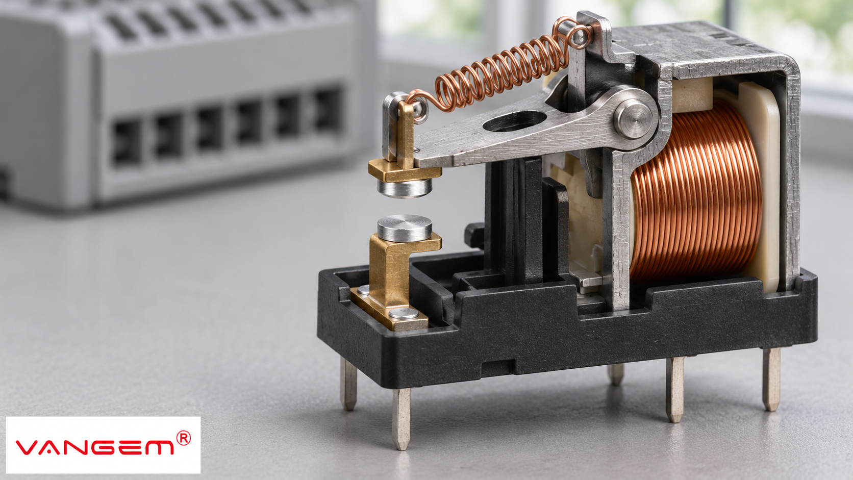
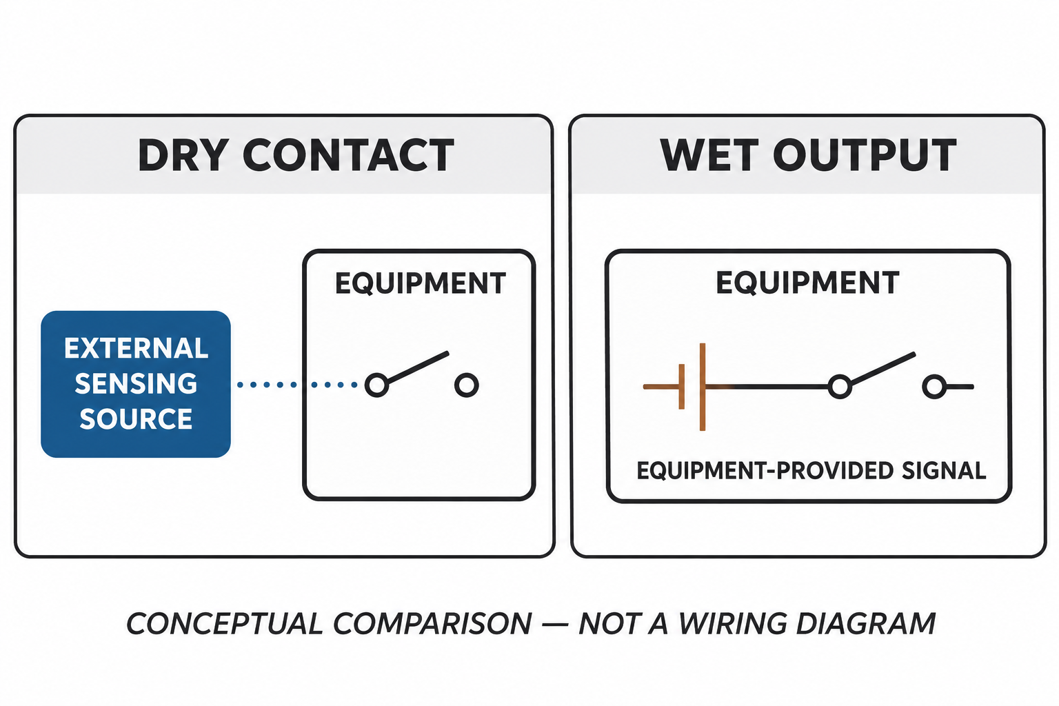
A dry contact is a switch contact that does not provide its own signal power. An external sensing circuit supplies the voltage used to detect whether it is open or closed. A wet contact, or voltage output, provides a powered signal from the equipment. The useful distinction is where the signal power comes from, rather than whether a connected wire happens to have voltage on it.
That distinction helps an integrator compare an equipment output with a monitoring input. It does not establish a universal voltage, a safe working condition or compatibility between two products.
What makes a dry contact dry?
A potential-free or volt-free output offers a contact for another circuit to monitor. The receiving controller may provide the sensing supply, or an external supply may serve that purpose. The particular input and output documentation determines which arrangement applies.
Once connected, a dry contact can carry the externally supplied sensing voltage. Calling it dry therefore does not mean every terminal must remain at zero volts. It describes the output’s relationship to its own power source.
Consider a generic equipment-status output and a separate monitoring controller. The first question is whether the equipment offers a contact closure or delivers a voltage signal. The second is what the controller input expects. Identifying both roles is more useful than choosing a cable because two terminal descriptions both contain the word “alarm.”
A dry-contact designation also does not establish the insulation or isolation performance of the complete interface. Any isolation claim needs its own documented scope.
Dry contact vs wet contact: compare the source
Manufacturers do not always use dry and wet in exactly the same way. The output description and input specification take precedence over a shorthand label. This comparison separates the questions that each document should answer.
| Question | Dry-contact output | Wet or voltage output |
|---|---|---|
| What does the equipment offer? | A switching contact without its own signal supply. | A powered signal associated with the equipment. |
| Where does sensing power come from? | The receiving input or a separate external circuit, as documented. | The equipment output; the receiver must accept that signal. |
| What remains to be checked? | Contact ratings and the receiving input’s sensing requirements. | Signal type, level and receiving-input requirements. |
| Does the label establish NO or NC? | No. Reference contact state is a separate description. | No. Powered-signal behavior also needs its own description. |
NO and NC answer a different question
Normally open (NO) and normally closed (NC) describe a contact’s defined reference state. A normally open switch contact is open when unactuated and closes when actuated. A normally closed contact behaves in the opposite direction. For a relay, the documentation should identify the applicable coil or reference condition.
Dry versus wet describes the power source; NO versus NC describes state. A potential-free output can therefore require a further choice about its contact configuration. Neither description replaces the other.
The monitoring system also needs a definition of what each state means. An open contact might represent a normal condition or an alarm, depending on the application. NC alone is not proof that the complete monitoring arrangement is fail-safe.
Read both sides of the interface
An interface review can begin with four documentary questions. These do not require guessing a terminal connection or assuming a typical signal voltage.
Who supplies the sensing signal?
The output manual should state whether the output is potential-free or powered. The input manual should state whether it supplies sensing power or expects an externally supplied voltage. Keep those two statements together when comparing devices.
Which state represents the condition being monitored?
Record the reference contact state and the intended normal and alarm states separately. This makes the required behavior explicit instead of leaving it hidden inside a NO or NC abbreviation.
Are the documented electrical limits compatible?
The presence of a contact is not enough. Compare the output’s documented switching limits with the input requirements. If the equipment offers a powered signal, its signal type and level must be supported by the receiving input.
What isolation is actually documented?
An input module’s isolation provisions are separate from the dry-contact label on an output. Ask which parts of the interface the stated isolation covers. A blank specification should remain an unanswered question, not become an assumed capability.
For example, a requirement that says only “monitor the alarm contact” leaves both signal-power origin and state behavior unresolved. A clearer requirement identifies the offered output, the receiving input and the defined alarm state. The equipment manuals can then establish the remaining electrical conditions.
Apply the distinction to equipment monitoring
For a surge protective device, local visual indication and a remote monitoring interface should be treated as separate requirements. A photograph of an indicator window does not establish the presence, configuration or rating of remote contacts.
Wanze’s AC surge protection device category provides a starting point for identifying a relevant product family. If remote status monitoring is needed, request confirmation for the exact model and configuration, together with its interface documentation.
A useful request describes the receiving system and the status that needs to be detected. The supplier can then confirm whether the offered model provides a suitable interface, rather than leaving a generic “dry contact required” note to carry the whole specification.