
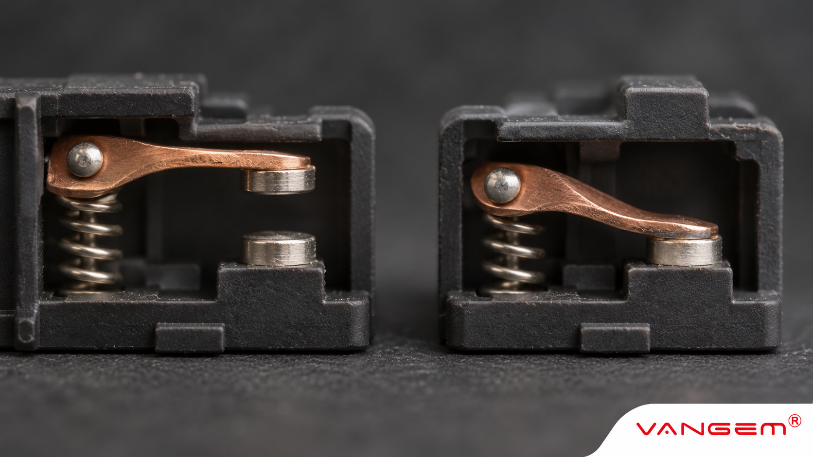
N/O means normally open: a contact is open in its specified reference condition and closes when operated. N/C, or normally closed, describes the opposite basic behavior. The important word is “reference.” These labels describe a contact state, rather than the usual state of a machine, a healthy process or a powered signal.
Reading a drawing starts with that distinction. A contact can be closed while the machine is stopped, and an open contact does not by itself prove an alarm.
What is N/O on a switch or relay?
A normally open contact interrupts its electrical path in the defined unactuated state. Operation brings the contact surfaces together, connecting that path. Closing a contact does not establish that current is flowing: a complete circuit and an appropriate power source are separate requirements.
For an ordinary spring-return switch, the reference condition is generally the unactuated position. A relay drawing may instead specify the de-energized coil condition. The manufacturer’s diagram identifies the reference appropriate to that device.
That qualification matters for devices with retained states. “No power” is not a universal way to identify the drawn position of a latching relay. Its documentation may describe a particular set or reset condition. First establish the reference, then read what operation changes.
Normally closed vs normally open: compare both states
An NC contact connects its path in the reference condition and opens on operation. The two labels make a useful comparison only when the reference and the operation are the same.
| Contact | Specified reference state | After operation |
|---|---|---|
| NO / N/O | Open path | Closed path |
| NC / N/C | Closed path | Open path |
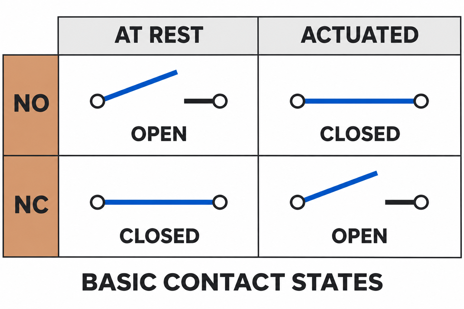
The table describes basic contact behavior. It does not assign an alarm meaning, supply voltage or electrical rating. A control system can interpret the same contact state differently according to its documented logic.
For example, a monitoring input may treat an open path as a reportable condition. That interpretation comes from the application, rather than from the letters NO or NC. Keeping those layers separate prevents a vocabulary definition from becoming an unsupported diagnosis.
Read COM and changeover labels separately
NO and NC may appear alongside COM on a changeover contact. COM identifies the common connection in that contact arrangement. It is not a general instruction to connect the terminal to protective earth, neutral or a particular supply.
Contact-form terminology supplies another way to describe the arrangement. Form A describes a normally open contact; Form B describes a normally closed contact. Form C describes a changeover arrangement. These names help identify the contact function, but the actual terminal identities still come from the model’s drawing.
A Form C label alone does not establish a universal pin number or every detail of switching sequence. It also does not establish the allowable electrical load. Contact voltage, current and switching ratings remain separate specifications that must match the proposed interface.
Normal does not mean normal production
A machine’s everyday operating condition may involve an actuated switch or an energized relay. Its contact can therefore spend most of its working life in the opposite state from the drawing’s reference condition. That does not change the contact’s NO or NC designation.
The same distinction applies to words such as healthy, fault and alarm. They describe the process or the control system’s interpretation. NO and NC describe the contact relative to a stated condition. Neither designation, on its own, establishes a fail-safe system.
State retention introduces a further question. A latching device can retain a state after an operating pulse; a single-stable device returns according to its operating design. The separate latching relay explanation covers that distinction. For either design, the manufacturer’s specified reference remains essential when interpreting a schematic.
A short sequence for reading the drawing
Start by identifying the exact device and drawing revision. A generic relay illustration may explain the vocabulary, but it cannot establish the connections of a similar-looking component.
Next, find the stated reference condition. Determine whether the contact is shown unactuated, with a de-energized coil, or in a specified retained position. If that condition is missing, ask for clarification before interpreting the contact state.
Then identify the contact arrangement and what changes when the device operates. Read the application’s signal definition separately: which input state represents a report, and which document defines that interpretation?
Finally, check the electrical interface against the device documentation. Contact-state labels do not answer whether a signal supplies its own voltage or whether a load is within the contact rating. This reading sequence supports a document review; it does not provide wiring instructions or establish a safety function.