
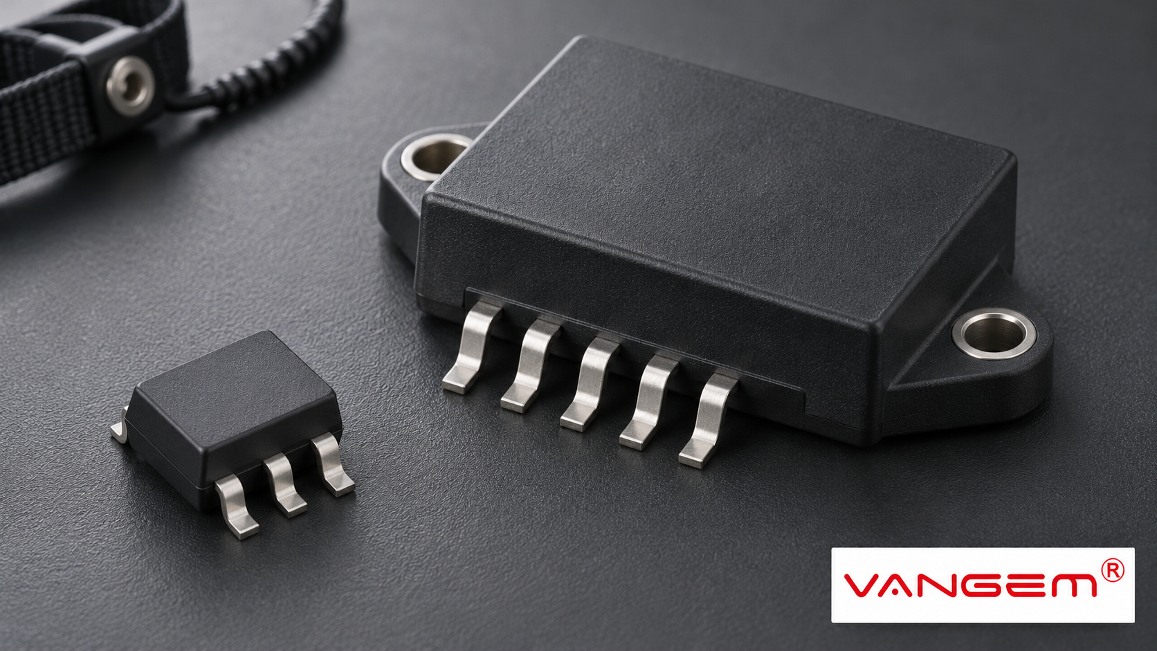
SiC packages are the physical housings and interfaces used for silicon carbide power devices. SiC identifies the semiconductor technology; it does not name one package shape, terminal arrangement or cooling method. Devices are offered as discrete components and as power modules with different integration scopes.
A useful comparison therefore starts with what is inside the offered item and what the surrounding system must still provide. Appearance alone cannot answer those questions.
SiC packages differ in integration scope
Discrete devices are commonly supplied in through-hole or surface-mount forms. A power module can integrate multiple power devices and interconnections into one assembly. The actual internal circuit depends on the model.
| Package approach | What to identify | What remains to review |
|---|---|---|
| Through-hole discrete | Exact device, package drawing and terminals. | Board, drive and cooling interfaces. |
| Surface-mount discrete | Footprint, contact arrangement and thermal path. | Board construction and mounting conditions. |
| Power module | Internal circuit and integrated functions. | External electrical, control and cooling interfaces. |
A package-family name such as TO-247 helps locate a drawing, but it is not a complete device specification. Nor does the word module establish that a driver, every protection function or the required cooling system is included.
The integration boundary should be explicit in the offered documentation.
Switching performance includes the surrounding loops
A fast semiconductor does not operate independently of its package and circuit connections. Gate-loop and power-loop parasitics can affect switching behavior. The package is one part of that electrical environment.
Some devices provide a separate source-reference connection, often called a Kelvin source, for the gate-drive reference. This feature concerns the relevant connection path; its presence and terminal identity must be confirmed for the exact device.
It does not justify copying a pin assignment from another package or promising a fixed reduction in switching losses. A comparison needs the documented devices and test conditions, rather than a favorable result detached from its setup.
This explanation identifies review topics. It does not prescribe gate-drive values, a PCB layout or a power-converter design.
The thermal path extends beyond the package outline
Heat must pass through the relevant package and mounting interfaces into the surrounding thermal arrangement. A package’s external dimensions do not, by themselves, describe that complete path.
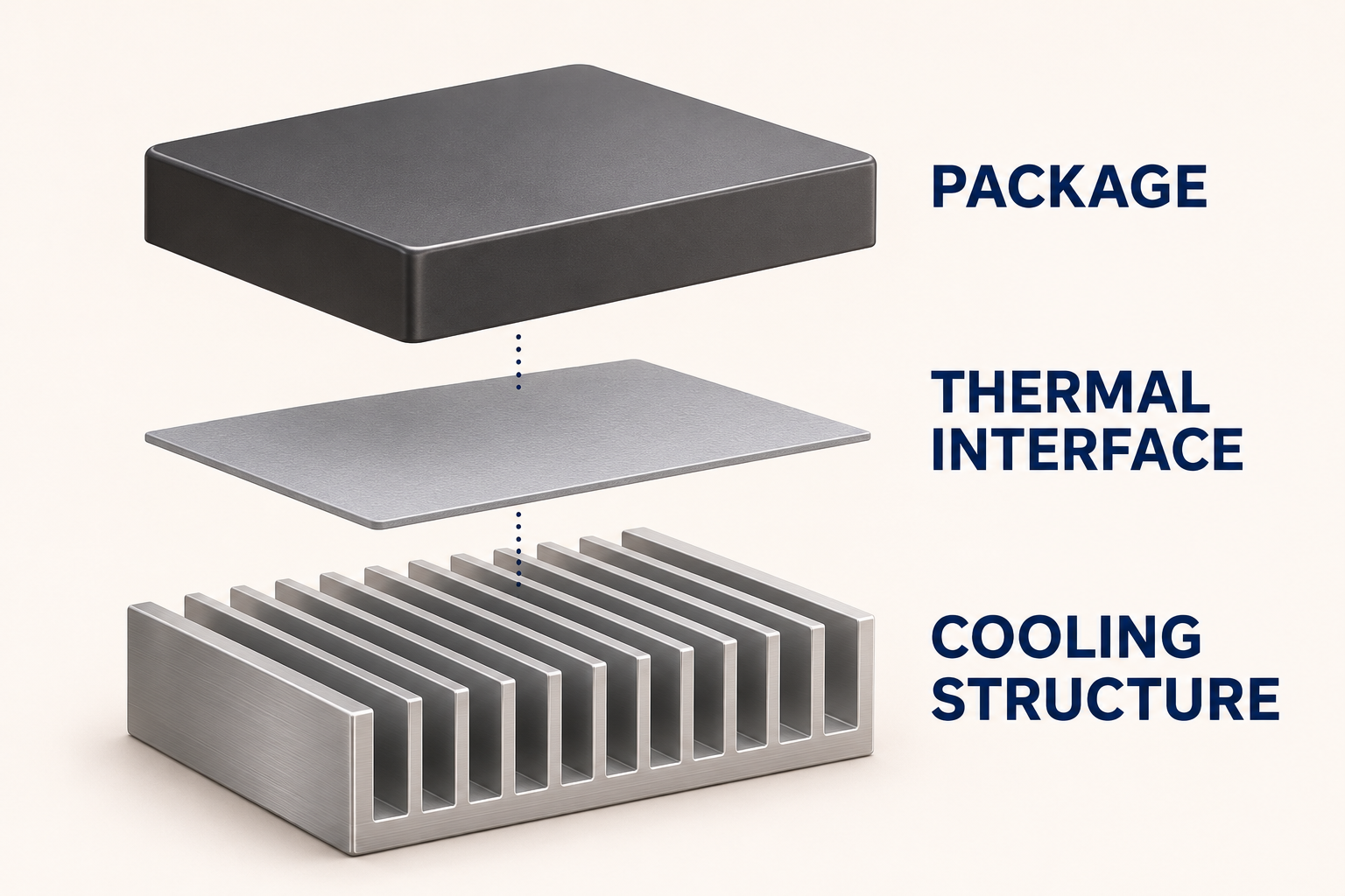
Read the manufacturer’s stated thermal quantities with their defined boundaries and conditions. A value for one package interface should not silently become a claim about the complete equipment assembly.
The mechanical drawing and mounting documentation matter alongside the electrical datasheet. Their purpose is to describe the offered item and its interfaces. They should not be replaced by a generic picture of a similarly sized component.
The illustration separates those interfaces without assigning temperatures, dimensions or a cooling-performance result.
Compare the documents before comparing the footprint
Begin with the exact part identity and revision. Then identify whether the offer covers a discrete device or a module, and obtain the corresponding circuit and package drawings. A shared outline is not sufficient evidence of interchangeability.
Next, separate the electrical review from the mechanical and thermal review. Which terminals and functions are actually provided? Which operating and test conditions accompany the stated performance? Which interfaces must the surrounding system provide?
For a hypothetical module quotation, the buyer may need to clarify whether the offered assembly includes only power devices or additional functions. For a discrete-device quotation, the relevant question may instead concern a particular footprint or source-reference arrangement.
These are different evidence requests. A single claim that one package is smaller, faster or easier to integrate cannot settle them without its conditions. Compare the complete proposed configuration rather than an isolated adjective.
Keep semiconductor selection separate from surge protection
Power-conversion equipment and its surge-protection interfaces are different selection tasks. A semiconductor’s SiC technology does not establish the surge requirements of an entire PV installation.
Wanze’s verified catalog includes solar PV surge protection devices. It does not establish a Wanze SiC semiconductor line or inverter-design service. For an SPD enquiry, identify the actual electrical interface and request the offered model’s documentation.
This article explains adjacent power-electronics terminology; it does not recommend a semiconductor model or claim a finished system’s performance.