

Line is the supply side of a device; load is the side feeding the equipment or circuit beyond it. In a load vs line comparison, the reference point matters: the same connection can be on the load side of one device and the line side of the next. These words describe a relationship, not a permanent wire color.
A drawing becomes easier to read when each label names the equipment it belongs to. “Load side of the disconnect” gives more information than “load wire.” It identifies where the connection sits in the power path without pretending to describe the entire circuit.
Load vs line describes direction relative to equipment
Start with a single device drawn between a source and a downstream load. Its incoming supply connection is the line side. Its outgoing connection toward that load is the load side. Leviton uses this distinction when explaining the two sets of terminals on a GFCI receptacle.
The word load also names the equipment receiving electrical power. A motor can be a load; a connection upstream of that motor can be the load side of a protective device. The equipment and the connection are related, but they are not the same thing.
| Term on the document | What it tells you | What it does not establish |
|---|---|---|
| Line side | The connection toward the supply, relative to the named device | A universal physical position or conductor color |
| Load side | The connection toward downstream equipment, relative to that device | The identity or operating demand of every downstream load |
| Electrical load | The equipment or circuit receiving power | Which terminal another device calls LINE |
The same connection can be load side and line side
Consider this original reading example: a source supplies Device A, Device A supplies Device B, and Device B supplies a load. The example deliberately leaves out physical terminals and conductor details. Its purpose is to establish the reference point for each label.
The connection from the source to A is on A’s line side. The connection from A to B is on A’s load side, because it leaves A toward downstream equipment. That same connection reaches B on B’s line side, because it supplies B. The final connection leaves B on its load side.
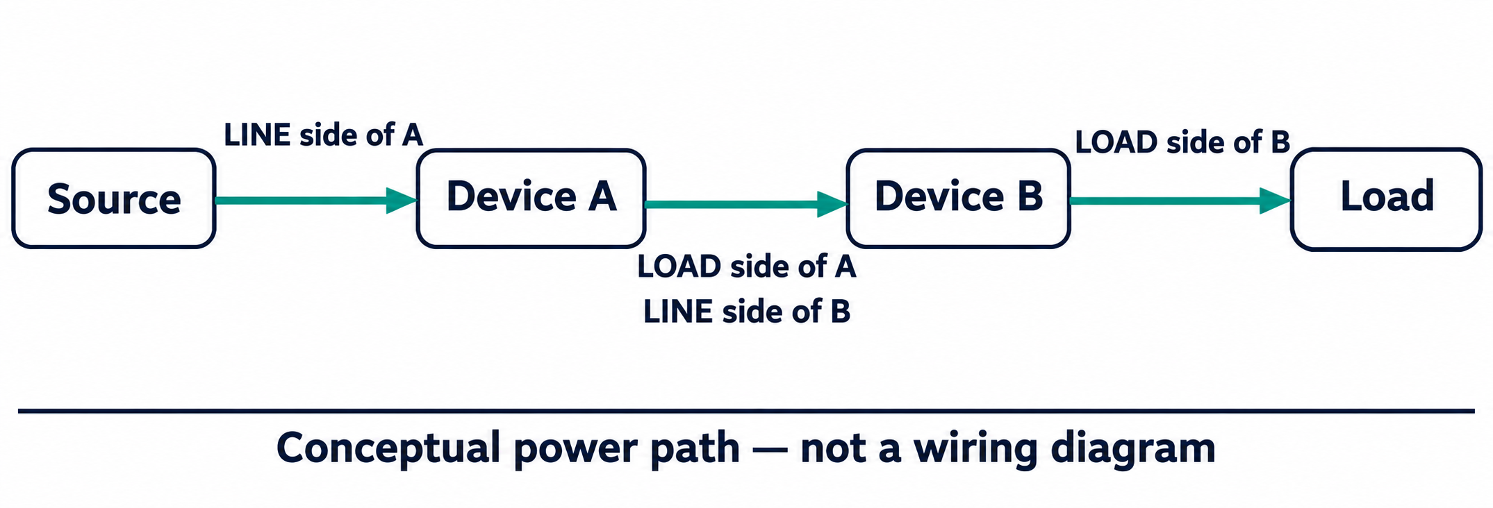
There is no contradiction between those descriptions. The drawing has changed its point of reference, not the role of the equipment. For a specification review, a useful annotation therefore names both ends: “A outgoing connection to B incoming connection.” It is less ambiguous than a note that simply says “connect to load.”
Read the actual markings before assuming a terminal arrangement
A familiar diagram does not establish a universal terminal layout. Top and bottom, left and right, and LINE and LOAD are different kinds of information. The first pair describes a position on the page or equipment; the second describes a connection’s role. A rotated drawing can change its appearance without changing that role.
Device documentation also matters. UL’s molded-case circuit-breaker marking guide discusses breakers with and without line/load markings. That distinction is a reason to read the actual product instructions, not a reason to assume that any unidentified device can be reverse-connected.
The GFCI example has its own specific boundary. Leviton explains that its referenced SmartlockPro devices include a feature that prevents operation after line/load reversal. That behavior belongs to the described product family. It should not be generalized into a claim about every switch, breaker, receptacle or surge protector.
For a document review, retain the manufacturer’s exact terminal designations alongside the drawing. A handwritten “input” or “output” note may clarify a relationship, but it should not erase the label that lets a reviewer find the correct instruction sheet.
Line and load are not substitutes for neutral or voltage-path labels
Two questions often become mixed together: where a connection sits relative to equipment, and which conductor or electrical path a label identifies. Line/load terminology addresses the first question. Labels such as neutral, L–N and L–L address different information.
NEMA’s surge-protection glossary uses L–N for a line-to-neutral relationship and L–L for a line-to-line relationship. Those labels describe the conductors between which a condition or protection mode is considered. They do not mean “incoming to outgoing.” A diagram can therefore need both a device-side description and a conductor-path description.
Wire color adds another layer rather than resolving the reference point. A color visible in a photograph cannot, by itself, establish which named device a line/load note refers to. Reading the equipment label and its documented relationship avoids trying to answer a diagram question from appearance alone.
Keep the power path separate from the surge-protection branch
The distinction becomes useful when a drawing includes surge protection. NEMA distinguishes a one-port SPD from equipment that also provides connections for supplying downstream loads. The word load in a general power-flow sketch does not make every protective component a device through which the normal load supply must pass.
When continuing into Wanze’s AC surge protection devices, keep the equipment connection drawing and the system power path as separate questions. This vocabulary explanation does not select a connection arrangement or a model. It helps identify what the actual model drawing still needs to answer.
A useful equipment record contains the device name, the exact terminal label, the upstream or downstream equipment named on the drawing, and the instruction-sheet reference. If one of those is missing, the unresolved item is identifiable. That is a better starting point for an engineering review than relying on an isolated “line wire” label.
References
Leviton — GFCI line/load terminology and reversal behavior
UL Solutions — Molded Case Circuit Breaker Marking and Application Guide, line/load identification
NEMA Surge Protection Institute — Load, conductor paths and one-port SPD terminology