

An MCB circuit breaker symbol identifies a breaker function on an electrical drawing; the drawing legend explains the particular representation. The symbol alone does not establish the device’s model, rating or installation suitability. Read it together with its tag and the equipment information referenced by the drawing.
MCB means miniature circuit breaker. A schematic represents a function rather than reproducing the plastic housing on a rail. A familiar-looking contact therefore needs context before it can be identified as an MCB, a different breaker or another switching device.
How to read an MCB circuit breaker symbol
Begin with the legend supplied with the drawing set. It connects the symbol used on that project to the component description. The nearby identifier then connects that component to an equipment list or another drawing reference. These are separate reading steps, even when the graphic and its text appear close together.
The illustration below separates them deliberately. The contact drawing is a generic teaching sample, not a reproduction of a particular IEC or ANSI library entry. The hypothetical tag CB-A names the item in the example; the dashed arrow points to documentation, not to another electrical connection.
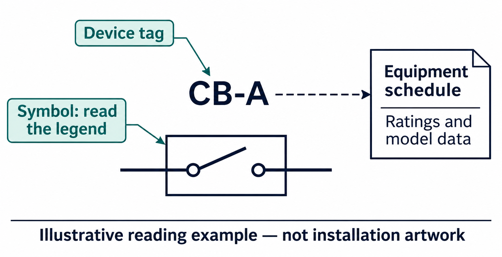
If a legend calls a representation a miniature circuit breaker, that description is the starting point. If the legend only identifies a general circuit breaker, the drawing has not yet established its construction or exact product family. The equipment schedule supplies the next part of the answer.
IEC and ANSI examples need their drawing context
IEC 60617 is the collection for graphical symbols used in electrotechnical diagrams. Its public database description includes switching and protective devices. That scope helps identify the right reference collection; it does not mean that every drawing found online reproduces a specific entry accurately.
The IEC technical committee also distinguishes diagram symbols from symbols used on equipment. IEC 60417 concerns the latter collection. A mark printed beside a physical control and a component symbol used in a circuit drawing can therefore serve different purposes, even when both appear in electrical documentation.
For North American examples, The referenced manufacturer design guide discusses standardized drawing symbols and shows several breaker representations. Its explanation treats a basic component drawing and added nomenclature as complementary information. A drawing can communicate more by adding text or related elements than by changing the outline alone.
A useful comparison consequently records which legend each example came from. Calling one small sketch “IEC” and another “ANSI” without that context removes the information needed to interpret them. The relevant drawing reference should accompany a symbol comparison, especially when documents from different equipment suppliers are being reviewed together.
A device tag is different from a function number
A project tag identifies an item within that project’s naming system. In the illustration, CB-A is an invented identifier used only to demonstrate that relationship. Another drawing can use a different convention. Its meaning should be read from the project documents rather than inferred from the typography.
A function designation answers a different question. The guide gives the example of the number 52 inside a square breaker representation in a medium-voltage one-line context. In that example, 52 identifies an AC circuit-breaker function. It is not an ampere rating, and the example does not establish that every miniature breaker is drawn as a square containing 52.
This distinction prevents two common reading errors: treating every nearby number as a rating, and treating every breaker representation as an MCB. The shape, designation and context need to agree before the equipment description is complete.
| Item being read | Question it answers | Where to continue |
|---|---|---|
| Symbol and legend entry | What function does this drawing represent? | The drawing’s symbol legend and referenced library |
| Project device tag | Which item does this record identify? | Equipment list and cross-reference |
| Function designation | What function does the designation describe here? | The convention cited by the drawing |
| Rating or model information | What equipment data has actually been specified? | Equipment schedule and manufacturer documentation |
A worked reading record is more useful than a shape guess
Suppose a drawing shows the illustrative contact assembly tagged CB-A. Its legend describes that representation as a miniature circuit breaker. The equipment list has a corresponding CB-A entry, but the product data has not yet been attached. This is a hypothetical documentation example, not an installed system.
The reader can already identify the drawing item and the type of component the legend intends. The reader cannot yet identify its exact model or confirm its electrical ratings. Writing down those two conclusions separately keeps a useful partial reading from becoming an unsupported equipment decision.
Now imagine a second drawing showing a square marked 52. Its legend and context identify a different breaker representation. The shared word breaker does not make the two items interchangeable. The second drawing needs its own identifier and equipment-data reference.
A compact review record can therefore contain the drawing number, the legend description, the device tag and the linked equipment entry. A missing entry becomes a specific request for documentation. Replacing it with a generic internet symbol chart would leave the original question unresolved.
Keep symbol identification separate from product selection
A correctly identified symbol is a starting point for understanding a drawing. It is not a substitute for the product data needed to select equipment, and it does not show that another type of protection performs the same job.
For example, Wanze’s AC surge protection devices belong to the surge-protection part of a system review. A breaker entry in the drawing does not, by itself, describe the SPD entry or establish how a particular SPD should be connected. Each component needs its own documented identity.
References
Eaton — Basics of Power System Design, standardized drawing symbols and breaker examples, page 10
IEC — Public scope of the IEC 60617 graphical-symbol database