

A dual inline package (DIP) has two parallel rows of external leads. The term identifies a package arrangement, not the electronic function inside it. A DIP component may contain a timer, an amplifier or another circuit, and the package name alone does not tell you what its pins do.
For component identification, dual inline package meaning concerns the external lead arrangement. The device pinout and mechanical drawing supply different details. Each document answers a different question, and none should silently replace the others.
Dual inline package meaning in a component description
“Dual” refers to the two lead rows. The label PDIP adds the plastic-package qualifier. It does not specify one universal body width, lead spacing, pin count or electrical rating. Those details belong to the specific part and package documentation.
A pin-count label is also incomplete on its own. “Eight-pin DIP” identifies a terminal count and broad arrangement, but it does not establish the function of pin one, the full body dimensions or compatibility with an existing circuit.
Texas Instruments’ NE555 documentation illustrates the distinction. Its device information lists the P package as PDIP with eight pins, alongside other package options for the timer family. The same datasheet then supplies a separate pin-configuration view and pin-function table. The package option and the connections are related information, but they are not the same information.
Read the stated view before assigning pin numbers
A pinout diagram must be read in the view named by the manufacturer. The TI NE555 eight-pin diagram is explicitly a top view. Its orientation feature and first-pin position give the reader a reference for following the numbering around the outline.
In that example, the left side runs from pin one at the top to pin four at the bottom. The right side runs from pin eight at the top to pin five at the bottom. Reading across from the bottom of the left row, rather than restarting at the top right, preserves the displayed numbering sequence.
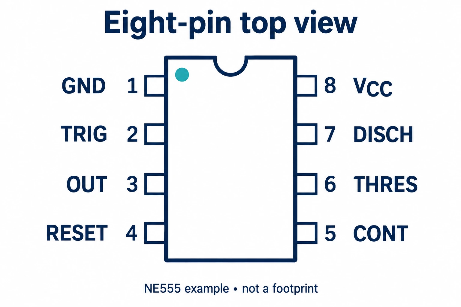
The source identifies pin one as GND, pin two as TRIG, pin three as OUT and pin four as RESET. On the other side, pin five is CONT, pin six is THRES, pin seven is DISCH and pin eight is VCC. These are NE555 assignments, not a universal rule for every eight-pin DIP.
A view label is especially important when moving between a component image, a pinout and other assembly documents. A photograph taken from a convenient angle does not necessarily use the manufacturer’s drawing orientation. Keep the reference view explicit instead of guessing which side of the package is being shown.
Separate “same circuit” from “same package”
Two checks prevent a familiar-looking package from being treated as proof of equivalence. One asks whether a device family has several package options. The other asks whether different devices share a package category.
| Comparison | What the source example shows | What still needs checking |
|---|---|---|
| Same device family, different packages | The NE555 information lists P as PDIP and D as SOIC, among its options. | The exact orderable variant, package drawing and requirements for the intended assembly |
| Different devices, same broad package | Both NE555 and listed LM358 variants have an eight-pin PDIP option. | Device function, every applicable pin assignment and the remaining design requirements |
The second comparison is concrete. In the NE555 pin table, pin one is GND. In the LM358 pin table, pin one is OUT1, an amplifier output. A shared pin count and PDIP label therefore do not establish matching connections or interchangeable functions.
The first comparison has a different implication. Finding the right device-family name is not enough to select its mechanical form. A quotation should preserve the full manufacturer reference rather than replace the requested package option with a broad family description.
A pinout diagram is not a dimensional package drawing
A functional pin diagram tells the reader which named terminal occupies each numbered position. A mechanical drawing describes the physical package through the dimensions, views and conditions stated in that document. A simplified pinout should not be measured to create a footprint.
Keep those document purposes separate during a review. Use the device information to identify the relevant package option, the pin-function table to interpret the terminals, and the applicable mechanical and orderable information for the selected variant. Check the revision and scope of each source.
Where a drawing provides maximum, minimum or nominal information, retain the stated meaning rather than silently treating every value as an exact measurement. A missing dimension remains an open item; a value from a similar-looking package is not evidence for the selected part.
A clear comparison record can name the field under review, the original part’s source, the proposed part’s source and the unresolved difference. That makes it easier for the responsible reviewer to see whether a question concerns physical fit, terminal function or an ordering option.
Finish the identification with the complete part reference
A useful component handover includes the manufacturer and full orderable reference, the package option, the applicable datasheet revision and the drawing view being used. Add the relevant pin-function information when connections are part of the review.
If a proposed alternative is described only as “DIP-8,” request the missing identity before accepting the comparison. The same applies when a seller supplies a product photograph without the drawing or a family datasheet without identifying the orderable variant.
The package label gives the reader a starting description. A complete identification connects that description to the specific circuit, pin assignments and mechanical documentation. Keeping those links explicit is more useful than assuming that a recognizable outline means a matching component.
References
Texas Instruments: xx555 Precision Timers, SLFS022K — March 2026 revision; device/package information and the eight-pin top-view diagram.
Texas Instruments: Industry-Standard Dual Operational Amplifiers, SLOS068AB — October 2024 revision; listed package options and device-specific pin functions.