

A hybrid solar system combines photovoltaic generation, battery storage and coordinated power conversion, commonly alongside a grid connection. Solar energy can supply loads or enter storage for later use. However, a battery and a “hybrid” product label do not by themselves establish that a building will remain powered during an outage.
The useful starting point is the architecture: where AC and DC conversion occurs, which loads the system serves, and which operating modes its documentation supports. Those questions separate the system’s functions from the capabilities of any single component.
Hybrid solar system components have separate responsibilities
PV modules produce direct-current electricity. Inverters convert DC to alternating current for AC loads. Batteries store energy rather than create it, while controls coordinate the available sources and demand. These functions can be packaged in different products, so a component count alone does not explain the system.
| Function | Component or information | Question for the project record |
|---|---|---|
| Generation | PV modules and their conversion path | Where does generated DC become usable AC? |
| Storage | Battery and available energy | How much energy is available for the stated task? |
| Power conversion | PV, battery or shared conversion equipment | Which converter serves each energy path? |
| Coordination | Controls and documented operating modes | What happens when generation, demand or grid availability changes? |
| Load supply | Defined circuits or equipment group | Which loads are included in each operating mode? |
This functional description also makes equipment quotations easier to compare. One proposal may describe a shared inverter, while another uses separate PV and battery converters. The buyer needs to compare their supported functions rather than assume that the shorter equipment list is more complete.
A project record can identify the existing equipment separately from proposed additions. That distinction helps reveal whether the supplier is describing a new PV-plus-storage architecture or a modification to an existing installation. It also prevents an assumed function from disappearing between the system description and the equipment schedule.
AC and DC coupling describe where the paths meet
In an AC-coupled arrangement, the PV and battery conversion paths meet on the AC side. A PV inverter converts generation to AC, and a battery inverter handles conversion between the battery and that AC system. The coupling label identifies this relationship; it does not establish a particular backup capability.
In a common DC-coupled arrangement, PV and storage share a DC-side relationship before conversion to AC. DC conversion and charging electronics still have defined roles. The simplified diagram below groups those functions rather than implying that a battery can be connected indiscriminately to a PV source.
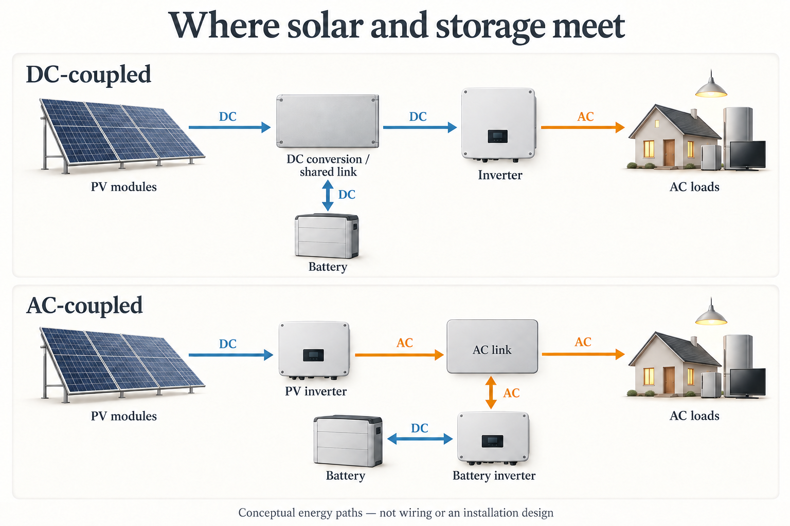
The US Department of Energy describes solar charging a battery either over DC or after conversion to AC. Dynapower’s technical overview similarly distinguishes separate AC-side converters from DC-coupled arrangements sharing inverter infrastructure. These descriptions explain topology, not a universal ranking of system efficiency or suitability.
For an equipment comparison, the project team can follow one energy path at a time: PV to loads, PV to storage, and storage to loads. Each path should name its conversion equipment. This makes the difference between an architecture drawing and a list of familiar product names visible.
The same diagram should distinguish an existing converter from a proposed one. Without that distinction, two suppliers can appear to offer the same “hybrid” system while making different assumptions about the equipment retained. A clear system boundary is more useful than treating AC or DC coupling as a verdict.
Backup operation needs its own description
Battery storage can support outage operation only within a system designed for that function. DOE explicitly qualifies grid-independent operation in this way. A normal energy-shifting mode and a documented backup mode are different capabilities, even when both use the same battery.
The following behavior matrix is a way to read a proposal. It describes the evidence needed for each condition, not a promise that every hybrid system behaves identically.
| Condition | Function being described | Evidence to request |
|---|---|---|
| Grid available; PV generation present | Generation supplies demand and may charge storage | The documented control priorities and conversion paths |
| Grid available; PV generation insufficient | Grid and available storage serve their permitted roles | Supported discharge mode and defined load group |
| Grid unavailable | Backup, if the system specifically supports it | Explicit outage-mode capability and the loads included |
| Grid unavailable; limited stored energy | Available energy constrains the supported duration | Starting energy, demand assumptions and any supported PV contribution |
For example, a quotation may state a battery’s energy capacity without naming the loads served during an outage. That leaves a material question unanswered. The reviewer cannot infer whole-building backup from the battery capacity or from a drawing that only shows normal grid-connected operation.
An operating-mode statement should therefore identify the condition, the supported function and the included loads together. It should also distinguish a documented capability from a future option. This is a scope comparison, not a procedure for implementing transfer, isolation or grid-independent control.
Battery energy and output power answer different questions
Energy capacity, commonly stated in kilowatt-hours, describes an amount of stored energy. Power, commonly stated in kilowatts, describes the rate at which energy is supplied or used. DOE treats these as distinct storage characteristics. Neither quantity can replace the other in an equipment comparison.
Consider an explicitly hypothetical example: a battery has 10 kWh of usable DC energy available at the start, and the included AC loads draw a constant 2 kW. Ignoring conversion losses and any new PV contribution, the energy-only calculation is 10 kWh ÷ 2 kW = 5 hours.
If only 80% of that assumed usable amount is available at the start, the example becomes 8 kWh ÷ 2 kW = 4 hours before conversion losses. These figures are bookkeeping illustrations, not predicted outage durations. They do not establish the converter’s ability to supply the load.
The important word is “available.” Nameplate battery capacity is not automatically the energy available for a particular event. The comparison needs a consistent starting-energy definition. Conversion losses and changing demand also prevent the ideal arithmetic from becoming a guaranteed runtime.
A useful proposal keeps three entries separate: available usable energy, supported output power, and the demand profile of the included loads. A statement such as “large battery” supplies none of those relationships. Recording the quantities with their units makes an omitted assumption much easier to identify.
Surge protection is a separate AC or PV-side task
A surge protective device, or SPD, addresses transient overvoltage. It does not store energy, coordinate battery charging or increase backup duration. Schneider Electric defines its purpose in terms of limiting or diverting short-duration voltage transients, rather than managing normal generation and demand.
Once the system paths are documented, the relevant product categories can be distinguished. Wanze’s solar PV surge protection devices concern PV-side transient protection. Its AC surge protection devices belong to the AC-side discussion. These are separate product pathways, not a recommendation to use the same device throughout a hybrid system.
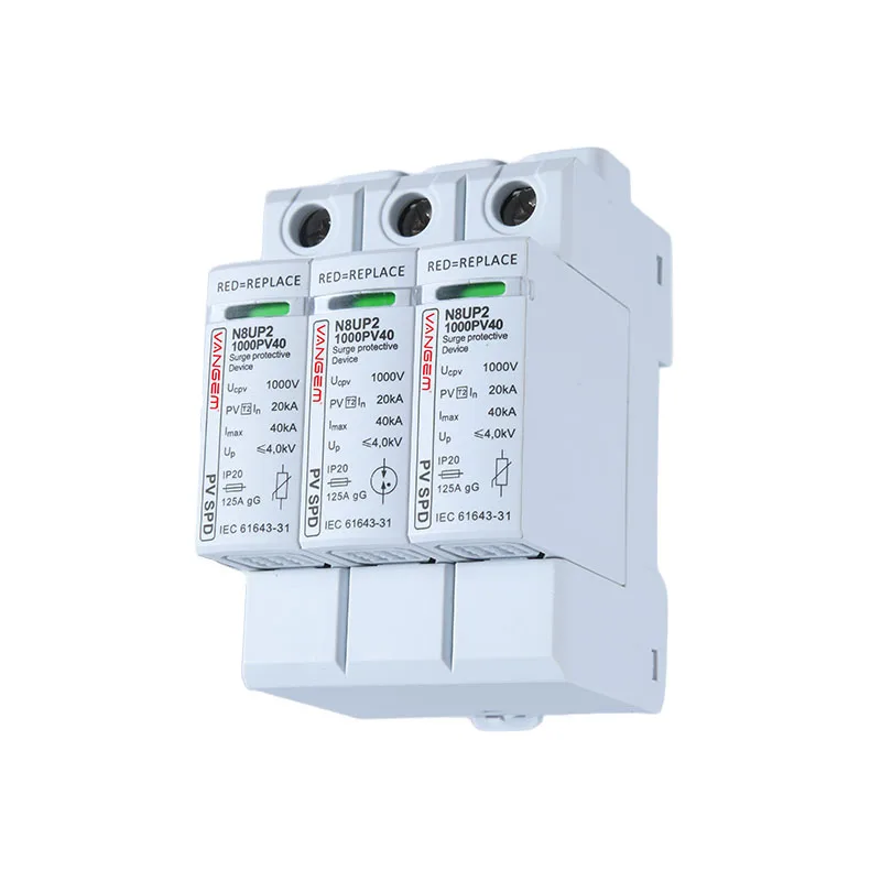
Wanze’s verified product scope here is AC and PV SPDs, not batteries, inverters or complete hybrid systems. A model-specific transient-protection review needs the actual circuit description and supporting equipment documents. A generic architecture illustration is not enough to confirm the application.
The strongest system description keeps the responsibilities visible: generation produces electricity, storage moves its use across time, converters connect the energy domains, and controls define supported operation. A separate protection review then addresses the documented electrical paths without attributing backup functions to an SPD.
References
- US Department of Energy: Inverters and Grid Services Basics
- US Department of Energy: Solar Energy and Storage Basics
- Dynapower: AC and DC coupling for solar plus storage — topology definitions, not historical economic estimates.
- Schneider Electric: What is an SPD?