

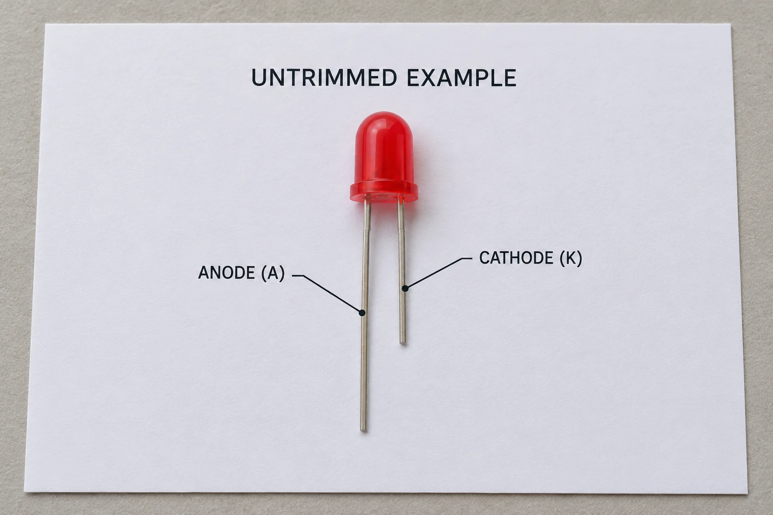
For LED light anode and cathode identification, start with the part’s datasheet and match its package drawing to the component. The anode is labeled A and the cathode K; conventional forward current passes from anode toward cathode. A longer lead can identify the anode on a familiar, untrimmed through-hole LED, but that clue loses its value when the leads have been cut.
What do LED light anode and cathode mean?
Anode and cathode name the LED’s terminals. They describe polarity, while a package drawing shows which physical lead or pad has each role. These are related questions, but they require different evidence: knowing what K means does not locate K on an unidentified component.
In a diode schematic symbol, the bar identifies the cathode side. The symbol describes the electrical relationship; its direction on the page does not tell you whether a real component’s cathode is its left, right, upper or lower lead. The package view supplies that connection between the schematic and the physical part.
SparkFun’s LED and polarity tutorials describe these conventions. They are useful introductory references, particularly when a symbol and a component photograph appear together. Keep the symbol’s terminal name separate from the photograph’s orientation. Rotating a component changes where a lead appears in the picture without changing whether that lead is A or K.
Lead length is a clue for an untrimmed package
For the familiar two-lead through-hole example, the longer untrimmed lead indicates the anode and the shorter lead the cathode. Some familiar molded packages also have a flat edge associated with the cathode. Both are physical clues to compare with the applicable drawing, rather than reasons to skip it.
| What you have | Useful evidence | What remains unresolved |
|---|---|---|
| Known, untrimmed through-hole part | Lead lengths and package marks matched to its drawing | Whether a generic convention applies before the match |
| Trimmed or equal-length leads | Part identity and documented package marks | Original lead length cannot be reconstructed from the cut ends |
| Surface-mount package | Model-specific pad map and indicated viewing direction | A mark’s meaning without the matching document |
| Multicolor package | Exact terminal diagram and common-terminal designation | Color-terminal order from appearance alone |
A loose component with shortened leads therefore needs a different answer from a new part in identified packaging. “The longer leg is the anode” answers the second case only when the documented package uses that convention. For the first case, an equal pair of leads supplies no original length evidence.
Match the package drawing to the part in front of you
A useful manufacturer example is Kingbright’s WP7113ID datasheet. Page one includes a package drawing with an explicit cathode callout. That callout identifies a terminal on that named part in the view shown. It does not establish a universal upper-lead or left-lead rule for other LED packages.
When reading such a drawing, locate the lens or body outline first. Then establish which way the leads extend and whether the document specifies a top, bottom or side view. Finally follow the cathode callout to its endpoint. This reading order keeps a correct label attached to the correct view.
For example, an LED pictured upright with its leads downward cannot be compared by page-left alone with a drawing whose body points sideways. Match the body and the documented reference feature before assigning a terminal. If the component identity is missing, even a perfectly readable drawing for another model does not close the gap.
The accompanying illustration isolates the familiar long-lead/short-lead convention so it is easy to recognize. It supplies no hidden internal-structure evidence and no proof of the identity of a loose LED.
Why SMD and RGB LEDs need their own pin map
SMD means surface-mount device: it describes the package form, not a universal polarity marking. A dot, notch or other visible feature becomes useful when the manufacturer’s drawing explains its meaning for that package. Copying a mark’s interpretation from a different part can attach a plausible label to the wrong pad.
RGB adds another distinction. SparkFun describes familiar RGB LEDs with separate color terminals and a shared terminal. In a common-anode arrangement the anodes share that terminal; in a common-cathode arrangement the cathodes share it. The shared connection’s role and the individual color-terminal order are separate details to obtain from the pin map.
A four-lead appearance alone does not give either answer. Nor should that familiar RGB arrangement be extended to every multicolor or addressable LED package. Use the architecture and terminal diagram stated for the identified model.
This makes the search question more precise. For an ordinary two-terminal part, the task is to locate A and K. For a documented RGB part, it includes identifying the common terminal and the color terminals. For an unfamiliar package, establish what the terminals represent before interpreting their order. The visible lead count helps describe the component; it does not replace its model identity.
Use an evidence order when marks disagree
Consider a parts-tray note that says “red LED,” a pair of equally short leads, and a flat-looking area on the lens. The note describes appearance, the cut ends remove the lead-length clue, and the apparent flat still needs a matching package reference. Assigning K at this point would hide the unresolved identity.
A more useful record separates observation from conclusion:
- Identity: record the part number or traceable packaging reference.
- Document: retain the corresponding datasheet and revision.
- View: match the drawing orientation and named reference feature.
- Terminal: record the A/K or pin designation supported by that match.
- Open question: retain any missing identification instead of replacing it with a visual guess.
This order also helps resolve an apparent conflict between a schematic and a photograph. Check whether one shows the circuit relationship and the other a differently oriented package. A documented pin map may reconcile them; if it does not, the discrepancy remains a document question. None of these observations requires powering the component.
Polarity identification does not diagnose an indicator system
Identifying an LED terminal does not explain what an assembled product’s indicator means. A colored window or light must be interpreted through that equipment’s own documentation. A component pin map cannot establish the equipment’s operating state.
If your task concerns protective equipment rather than a loose LED, Wanze’s AC surge protection devices provide a separate product-documentation route. Use the applicable model information for that equipment question. This guide does not identify a Wanze LED product or assign a universal meaning to SPD indicator colors.