

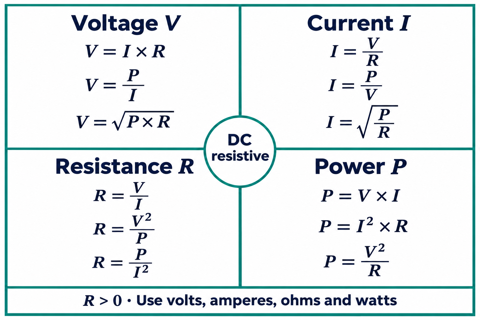
The Ohms law wheel groups voltage, current, resistance and power equations so you can choose a formula from the values you already know. The twelve forms below come from two base relations: V = I × R and P = V × I. They are rearrangements, not twelve separate physical laws.
This reference uses positive, steady DC quantities for a resistive model with a finite resistance greater than zero. Divisors must be nonzero. The examples are calculations, not instructions to build, energize or test a circuit.
Ohms law wheel: the twelve formulas
Choose the group for the quantity you need, then select the equation that uses your two known values. The chart is supplied as a full-resolution image that can be saved with the browser’s image controls. The table below provides the same equations as selectable text.
| Find | Known values | Equation |
|---|---|---|
| Voltage V | Current I and resistance R | V = I × R |
| Voltage V | Power P and current I | V = P ÷ I |
| Voltage V | Power P and resistance R | V = √(P × R) |
| Current I | Voltage V and resistance R | I = V ÷ R |
| Current I | Power P and voltage V | I = P ÷ V |
| Current I | Power P and resistance R | I = √(P ÷ R) |
| Resistance R | Voltage V and current I | R = V ÷ I |
| Resistance R | Voltage V and power P | R = V² ÷ P |
| Resistance R | Power P and current I | R = P ÷ I² |
| Power P | Voltage V and current I | P = V × I |
| Power P | Current I and resistance R | P = I² × R |
| Power P | Voltage V and resistance R | P = V² ÷ R |
The letters name quantities; the units make the calculation usable
V represents voltage, measured in volts. I is current, measured in amperes. R is resistance, measured in ohms, written Ω. P is power, measured in watts. Some references use E for voltage where this chart uses V; read the quantity definition in the document.
For direct substitution into this chart, express the inputs in volts, amperes, ohms and watts. Prefixes must be handled consistently. For example, kilo means one thousand. An input expressed in kiloohms cannot simply be entered as though the same number were already in ohms.
A useful calculation line therefore contains the quantity, its value and its unit before the arithmetic begins. Writing only a pair of numbers makes a unit error hard to distinguish from a formula error later.
Choose the equation by the inputs, not by its position on the circle
The circle is a memory aid. Its useful feature is that each group provides several routes to the same unknown. If voltage and resistance are known, the current group leads directly to I = V ÷ R. A power value is not required for that first step.
The power forms follow by substitution. Replacing V with I × R in P = V × I gives P = I² × R. Replacing I with V ÷ R gives P = V² ÷ R. Rearranging those expressions produces the remaining resistance and square-root forms.
The input pair must describe the same element and operating condition. Combining a whole-system voltage with the resistance of an unrelated component does not become valid because both values fit into a printed equation. Naming the element beside the calculation is often more useful than memorizing every segment of the wheel.
Worked example: voltage and resistance are known
Assume an ideal resistor has 24 V across it and a resistance of 8 Ω. These are hypothetical inputs. The required current follows from the voltage-and-resistance branch:
I = V ÷ R = 24 ÷ 8 = 3 A
Power can now be calculated using the voltage and the derived current:
P = V × I = 24 × 3 = 72 W
A second route provides a cross-check: I² × R = 3² × 8 = 72 W. Both routes describe the same assumed resistor under the same condition. Agreement checks the arithmetic; it does not turn the calculated dissipation into a component’s permitted power rating.
Worked example: power and resistance are known
For a different hypothetical resistive case, take 18 W and 8 Ω as the known values. The current group provides the square-root branch:
I = √(P ÷ R) = √(18 ÷ 8) = 1.5 A
The corresponding voltage is V = √(P × R) = √144 = 12 V. The power check is 12 × 1.5 = 18 W. Using the positive root is consistent with the magnitude convention chosen for this reference; it does not assign a physical current direction.
Unlike the first example, this route did not begin with a known voltage. Selecting a different branch of the wheel simply matched the available inputs. The underlying two base relations remained unchanged.
Keep the model assumptions beside the result
A correct algebraic result still depends on the model. This chart is not a general replacement for AC analysis involving phase or reactive effects, nor a model of nonlinear or transient device behavior. A formula sheet cannot supply a missing assumption about what kind of electrical quantity an input represents.
Zero values also need care. A rearrangement with zero in its denominator is undefined, even if another form of the base relation can still describe the limiting case. The wheel should not be used to force a numerical answer from an unsuitable branch.
For Wanze’s AC surge protection devices, selection belongs to the actual product and system documentation. The resistor calculations here explain basic relationships; they do not establish an SPD rating or a protection arrangement.
References
Fluke — Ohm’s law, quantity symbols and basic rearrangements