

A time delay relay changes its output according to a defined initiating event and a time interval. On-delay postpones an output turning on; off-delay postpones it turning off. The important distinction is what starts that interval: applying timer power, applying a separate signal, or removing that signal. A function name alone does not identify all three.
What a time delay relay actually delays
A timer description becomes easier to read when you separate its supply, trigger and output. The supply powers the timer. A trigger, where the function uses one, initiates an action while the timer is already supplied. The output is the state that the timing function changes.
Panasonic’s timer terminology distinguishes power-started and signal-started operations. This matters when a chart labels one row “power” and another “input.” A change on one row cannot automatically be treated as a change on the other.
Function families also extend beyond on-delay and off-delay. Littelfuse’s timing-relay listings separate delay-on-make, interval, single-shot and recycling families. These labels help locate a function description; they do not settle a particular model’s reset or retrigger behavior.
The useful question is which output transition is delayed relative to which event. A dial and a time range describe only part of that answer. They do not reveal whether the output waits before turning on or starts immediately and turns off later.
Compare on-delay, off-delay and interval by event
The following comparison describes basic functions with the required timer supply maintained, except where power removal is explicitly the initiating event. ON and OFF describe the function’s designated output state, not a universal physical contact-terminal assignment.
| Basic function | Event that starts timing | Output during the interval | At expiry |
|---|---|---|---|
| Power-on delay | Timer supply applied | Remains OFF | Turns ON |
| Signal off-delay | Trigger removed after output activation | Remains ON; timer stays supplied | Turns OFF |
| Power-on interval | Timer supply applied | Turns ON immediately | Turns OFF |
DARE Electronics describes these power-on and controlled-release sequences in its operation guide. Notice that a power-on delay and a power-on interval can begin at the same event while producing opposite output states during timing. The event alone therefore does not identify the function.
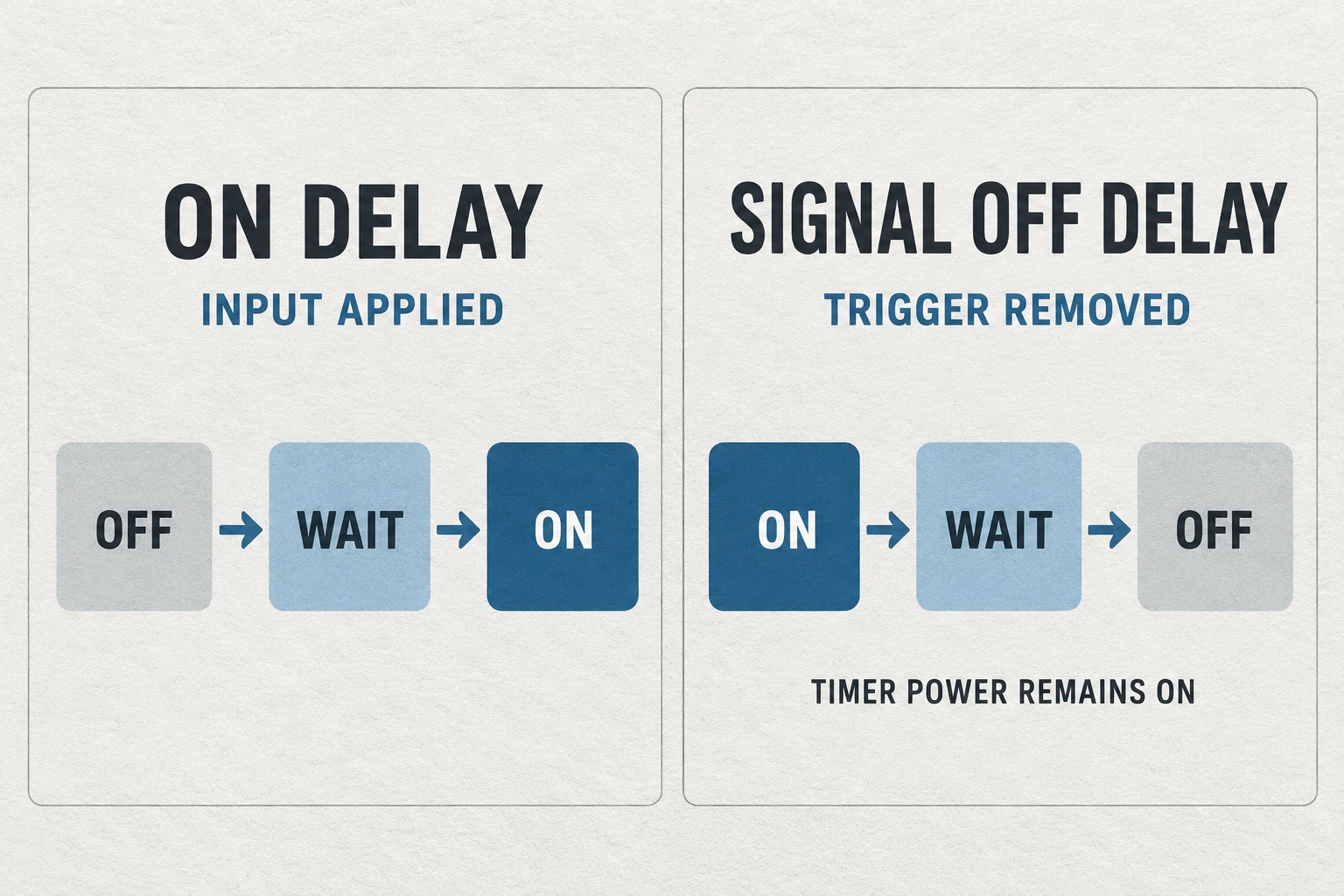
The illustration highlights delayed activation and delayed release. Interval timing adds a different question: does the output begin with the initiating event and end at timeout? Keeping these descriptions in event order avoids reading every timer as a device that simply “waits, then switches.”
Signal off-delay and power off-delay ask different questions
Removing a trigger and removing the timer’s supply are distinct events. In DARE’s controlled delay-on-release description, the timer remains continuously powered while the external control signal initiates release timing. Its true delay-on-release description instead starts timing when timer power is removed.
Panasonic likewise distinguishes signal off-delay from power-supply off-delay in its terminology. The distinction prevents a common reading error: assuming that any product labeled off-delay maintains its timed state after its own power disappears.
There is another boundary between a relay output state and the attached load’s energy source. A description of delayed contact release does not establish that an entire machine or load remains powered through a supply interruption. That is a separate system question.
For a document comparison, identify the event explicitly. “Trigger goes inactive while timer supply remains present” describes one case. “Timer supply is removed” describes another. A model’s timing chart and notes must address the intended case; the shorter phrase “after power off” leaves too much unspecified.
Read the timing chart from the initiating event
A timing chart relates events along a shared time direction. Read the row names before interpreting a rising or falling line. An upward output transition means something different from an upward supply transition, even when the two appear at the same position.
A compact reading record keeps the essential questions together:
- Supply: Is timer power present throughout the illustrated sequence?
- Initiation: Which event starts the timed interval?
- Output: What state does the designated output hold during timing?
- Expiry: Which transition occurs when the interval ends?
- Interruption: What does the description say about reset or another trigger before timeout?
The last question cannot be answered by the delay setting alone. For example, DARE’s described controlled-release function resets its release interval if the control returns before timeout. That behavior belongs to that described function; it should not be transferred to every interval or single-shot label.
Reset time also deserves its own reading. Panasonic distinguishes resetting from the timed operation. A document’s reset condition is not another name for its selected delay. Preserve both pieces of information when comparing function descriptions.
Resolve an ambiguous delay requirement before comparing models
Consider a hypothetical specification note: an output should remain on after the command ends, then turn off. Two catalog entries might both appear relevant because both mention a release delay. The note is still missing the condition that distinguishes them.
If “command ends” means the trigger becomes inactive while timer power remains available, the document comparison concerns a signal-controlled release sequence. If it means the timer loses its own supply, the comparison concerns a power-off-delay sequence. These are different descriptions even if the requested delay interval is identical.
A clearer requirement record names the initiating event, the supply condition and the required output transition. It also identifies the unanswered retrigger question: should another command restart timing, end it, or have no effect? This record describes the behavior to investigate without selecting a wiring arrangement or approving a device.
Now compare the complete chart with that record. A matching title is insufficient when the chart starts from a different event. Conversely, different marketing labels may lead to similar basic sequences, but equivalence still depends on the documented reset and supply conditions. The useful comparison is between complete behaviors, rather than between isolated delay values.
Keep timing control separate from surge protection
A timing function describes when an output changes. It does not establish protection against transient overvoltage or prove that a particular load and protective device work together.
For the separate protective-equipment question, Wanze’s AC surge protection devices provide a product-documentation route. Keep that enquiry distinct from the timer’s function chart. The generic timer shown here illustrates the article topic; it is not an identified Wanze relay product.
The document comparison is complete when the initiating event, supply condition, timed output and reset questions are explicit. Equipment selection still needs the applicable model documentation.