

The main types of circuit boards used in drones include flight controllers, electronic speed controllers (ESCs), power-distribution or power-monitoring boards, and communication or navigation modules. Some aircraft also use companion computers or payload electronics. Those names describe jobs. Rigid, flexible, rigid-flex and multilayer describe PCB construction, so they belong in a different part of a board’s description.
A useful identification record answers both questions: what does this assembly do, and how is its circuit board built? A label such as “multilayer drone PCB” answers neither the complete system question nor whether a replacement will work.
Types of circuit boards used in drones, grouped by function
Start with the assembly’s role in the aircraft. The following record separates the function from the document needed to identify it. Several rows may apply to one physical assembly.
| Functional description | Job to identify | Useful identification record |
|---|---|---|
| Flight controller | Receives inputs and sends flight-control commands | Board model, revision and supported interfaces |
| ESC | Controls motor speed through its supported interface | ESC documentation and supported command protocol |
| Power-distribution board | Provides the system’s power-distribution connections | Manufacturer’s power-path diagram |
| Power-management or monitor module | Supplies or monitors power, as documented | Supply and monitoring functions for that model |
| Receiver, navigation or telemetry module | Provides a particular command, sensor or data function | Module identity and host-interface specification |
| Companion or payload electronics | Performs an additional computing or mission task | Assigned task and interface to the aircraft |
ArduPilot’s input/output documentation distinguishes control inputs, sensors, power management, ESC or servo outputs, and telemetry. Its port descriptions also show why a connector name alone is insufficient: the individual autopilot documentation defines the actual ports and pinouts.
Use the table as an inventory prompt. An unfamiliar board should remain “unidentified” until its documentation supports a role, rather than being assigned a function from its color, size or position in a photograph.
Follow the power path and the command path separately
A command connection and a power-distribution connection answer different questions. The flight controller sends commands; an ESC uses a supported interface for motor-speed control. ArduPilot’s ESC guidance notes that communication and telemetry capabilities vary by ESC model.
A power-distribution board, or PDB, belongs in the power-path description. ArduPilot documents an architecture using a PDB alongside the autopilot and ESCs. A power-management module may instead be described by its regulated supply and monitoring functions. The manufacturer’s diagram establishes which functions a particular assembly combines.
For an identification exercise, draw two separate lines on paper: “command/data relationship” and “power relationship.” Assign each documented connection to the relevant line. This is a way to organize the system description, not a wiring diagram. A missing record on either line is a question for the board manufacturer, not a reason to guess from a matching connector.
Rigid, flexible and multilayer describe construction
Construction labels describe the board itself. A rigid PCB has a solid board section; a flexible circuit uses a bendable circuit substrate. A rigid-flex assembly incorporates rigid sections joined by flexible regions. Würth Elektronik describes integrated polyimide flex sections linking rigid portions in its rigid-flex technology.
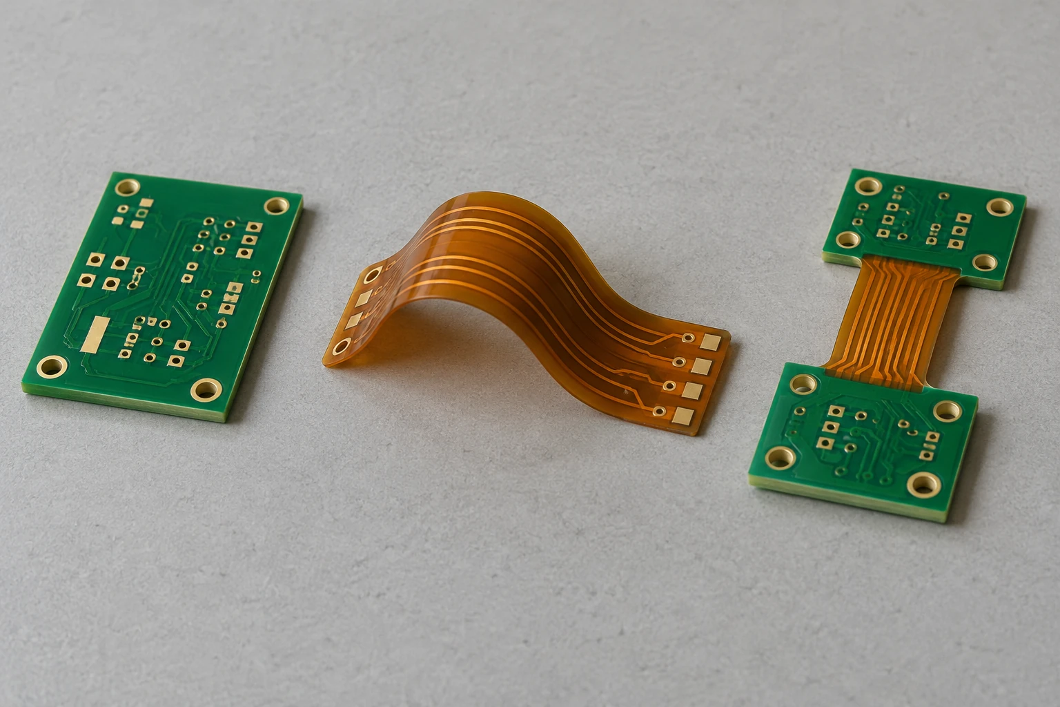
“Multilayer” adds another attribute: the board contains multiple conductive layers. It does not identify an ESC, flight controller or radio. Würth’s rigid-flex documentation includes layer-stack descriptions, illustrating why a construction record can contain both a rigid-flex designation and a layer description.
Record these attributes in separate fields. “Flight controller” belongs under function; “rigid multilayer PCB” belongs under construction. Neither description establishes a universal layer count, acceptable bend limit or aircraft suitability.
An integrated board still performs several jobs
Count functions before counting boards. In a hypothetical inventory, one assembly could be documented as combining control, power distribution and motor-control functions. Another aircraft could list those functions on separate assemblies. The inventory would describe a different physical arrangement without changing the meaning of each job.
That distinction matters when comparing a complete stack with a replacement board. A listing for one assembly may exclude a function included in another listing. Ask what is supplied, which functions remain elsewhere, and what documentation defines the connections between them.
A board count is therefore a poor comparison on its own. Keep the assembly boundary visible: the part being quoted, its included functions, and the documents that describe its relationship to the rest of the aircraft.
Decode a board listing before comparing alternatives
Consider the invented description “rigid multilayer flight-controller board with an external ESC interface.” “Flight-controller” identifies the intended function. “Rigid multilayer” describes construction. “External ESC interface” identifies a relationship that needs further documentation. None of those words names a proven replacement for a particular aircraft.
This fictional example leaves useful questions unanswered. The board revision, supported software, precise interface, included accessories and mechanical fit still need an authoritative record. A photograph and a short sales title cannot substitute for that record.
A comparison worksheet can use the following fields:
- Identity: manufacturer, complete part designation and hardware revision.
- Function: each documented task, including any combined functions.
- Construction: rigid, flex or rigid-flex, plus the documented layer description if relevant.
- Interfaces: the exact documents defining connections and supported protocols.
- Assembly boundary: included boards, cables, accessories and separately supplied parts.
- Unresolved questions: missing evidence and the party responsible for answering it.
Keep an identification record for each assembly
A useful comparison ends with a documented difference. For example, a fictional record might say: “Candidate A documents the flight-control function; Candidate B also lists power monitoring. Construction details are incomplete for both.” That conclusion identifies the evidence gap without turning it into a compatibility verdict.
Keep the original model documentation beside the completed worksheet. When a description changes, update the function and construction fields separately. This gives a buyer or maintainer a clearer question to send to the manufacturer than simply asking for “a drone circuit board.”