

VFD HVAC applications use a variable frequency drive to change an AC motor’s speed by adjusting its supplied frequency and voltage. In a commercial building, that motor may drive an air-handling fan or a circulating pump. The purpose is to match the mechanical output to demand rather than assuming full-speed operation is always necessary.
A drive is a control device, not a complete electrical protection system. Selecting an HVAC VFD and reviewing surge protection are related project tasks, but they answer different questions. A useful specification identifies the load, operating profile and electrical supply before choosing accessories.
VFD HVAC control: from incoming power to motor speed
A common VFD power stage has three main sections. A rectifier converts incoming AC into DC. A DC bus stores and smooths that energy. An inverter then switches it into an output suitable for controlling the motor. The output frequency and voltage are managed together for the intended motor application.
This explains why the input and output sides should not be treated as interchangeable. The incoming distribution supply feeds the drive; the drive produces a controlled output for the motor. A device intended for one side does not automatically belong on the other.
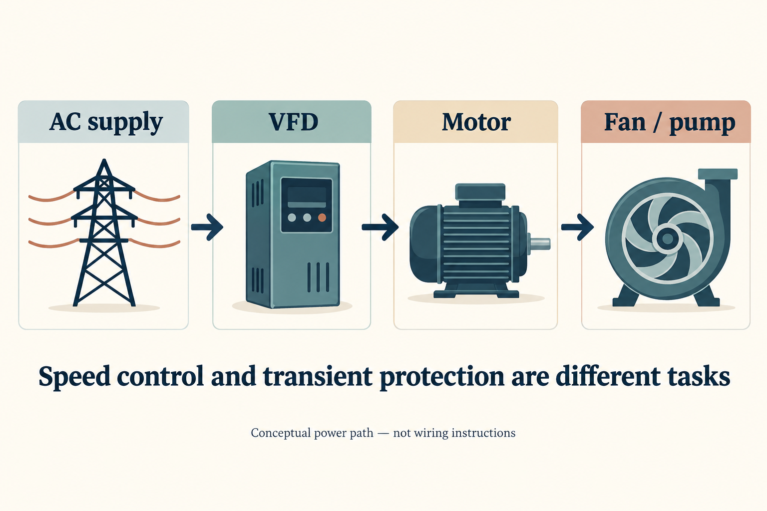
The drive also needs a reason to change speed. A controller can use information such as pressure or flow to determine the required operating point. The selected control sequence links that information to a speed command. A VFD’s presence alone does not establish which operating target the system will maintain.
For a buyer, the useful distinction is between a component capability and a commissioned system function. A drive can support variable-speed operation, while the actual result still depends on the motor, driven equipment and control strategy. These dependencies belong in the project description, not in an assumed universal benefit.
Fans and pumps need different demand descriptions
For an air-handling fan, the project team should describe the airflow requirement and how it varies during operation. For a circulating pump, the corresponding description concerns water flow and the hydraulic operating conditions. Both involve motor speed, but their acceptable operating ranges cannot be assumed identical.
A speed percentage is therefore not a complete requirement. The system designer needs to establish what the equipment must deliver at that speed. Manufacturer limits and the selected control sequence determine whether the operating point is useful for the actual system.
Describe the duty, not just the motor rating
A motor’s rated power does not say how many hours the HVAC system spends at each load. A building with prolonged reduced-demand operation presents a different evaluation from equipment that operates near its design point most of the time. The operating profile makes that difference visible.
An original screening record can be short: identify the fan or pump, state the required output, list the expected operating points and estimate the hours at each point. The equipment supplier can then identify missing limits or performance curves. This is more actionable than requesting a drive solely by horsepower.
The same record should identify what is known and what is estimated. A measured operating profile and an owner’s expectation are not equivalent evidence. Keeping those inputs separate lets the project team revise an assumption without treating an estimate as an established result.
Load-profile worksheet
This blank worksheet is for project data, not a set of assumed operating values. Record the equipment and comparison baseline above the table. Add one row for each operating point; use consistent flow units and a stated time period for the hours.
Fan or pump asset: __________ Comparison baseline: __________ Period covered: __________
| Operating point | Required flow and units | Speed, if known | Hours in period | Performance data reference | Measured or estimated; source |
|---|---|---|---|---|---|
| Point 1 | __________ | __________ | __________ | __________ | __________ |
| Point 2 | __________ | __________ | __________ | __________ | __________ |
| Point 3 | __________ | __________ | __________ | __________ | __________ |
Use the completed rows to support the energy estimate below. A missing speed or performance curve stays unknown rather than becoming a guessed value. The worksheet organizes inputs; it does not establish a safe operating range or calculate electrical savings by itself.
Estimate energy with a load profile, not a blanket percentage
The familiar cube relationship is a restricted model for centrifugal fans or pumps under suitable conditions, including negligible static lift. It relates the driven equipment’s shaft-power requirement to speed. It should not be applied indiscriminately to every pump, compressor or complete HVAC plant.
Consider an original hypothetical fan example. Assume the reference shaft-power requirement is 10 kW. Under the idealized relationship, reducing speed to 75% gives a relative power requirement of 0.75 × 0.75 × 0.75 = 0.421875. The modeled shaft-power requirement becomes 4.21875 kW, or approximately 4.22 kW.
That number is not a prediction of electrical input power at the building meter. Actual electrical input depends on the motor and drive efficiencies at the operating point. System characteristics and the output that the fan must deliver also matter. The example illustrates the model; it is not a promised saving for a customer’s installation.
Keep four parts of the estimate separate
- Required output: the airflow or water-flow duty the system must meet.
- Operating hours: time spent at each relevant load point, not just annual run hours.
- Equipment performance: the fan or pump curve and the motor/drive efficiency at those points.
- Comparison baseline: the existing or proposed arrangement against which the estimate is made.
A projected percentage without those inputs is difficult to audit. It may compare different operating duties or confuse shaft power with electrical input. Asking for the calculation basis is more useful than comparing two headline savings claims that do not describe the same system.
The final estimate should identify its evidence source and uncertainty. For example, supplier performance data and a measured duty profile support a different level of confidence from a simplified affinity-law illustration. Neither should be silently presented as the other.
Separate supply-side, drive and motor-side questions
The word “protection” can obscure several different engineering tasks. The table below is a responsibility map, not a list of accessories that every HVAC installation requires.
| Question | Relevant review | What not to assume |
|---|---|---|
| How should motor speed follow demand? | Drive control and HVAC sequence | An SPD cannot provide speed control. |
| Does the incoming AC system need transient-overvoltage protection? | Supply-side SPD application and coordination | A drive does not prove the distribution protection is complete. |
| How does PWM output interact with the motor and cable? | Drive, motor and cable documentation | A generic AC supply SPD is not an output-filter recommendation. |
| Is a harmonics measure needed? | The actual drive and power-system assessment | Surge suppression and harmonic filtering are not the same function. |
Pulse-width-modulated drive output can introduce motor-side voltage and bearing interactions. The US Department of Energy discusses these as drive-system design questions. Their assessment depends on the actual equipment and cable arrangement; this overview does not prescribe filter settings or motor-terminal connections.
Supply transients are a different concern. An SPD limits transient overvoltage within its intended application. Its presence does not demonstrate that motor-side waveform issues have been addressed. Conversely, a motor-side measure does not establish that the incoming distribution system has the required transient protection.
The practical handoff is to identify the location and the phenomenon being reviewed. “Protect the VFD” is too broad to resolve either. “Review input-system transients for this documented supply and drive” gives the supplier a bounded task without presuming the answer.
Prepare one project record before requesting protection accessories
A purchasing record should connect the HVAC duty to the actual electrical system. It does not need to reproduce an entire engineering design, but it should prevent different suppliers from making incompatible assumptions about the same equipment.
| Record field | Information to obtain | Decision it supports |
|---|---|---|
| Driven equipment | Fan or pump identity and performance information | Whether the proposed operating range serves the duty |
| Motor and drive | Exact models, input requirements and manufacturer documentation | Compatibility review rather than a horsepower-only match |
| Duty profile | Required outputs, operating hours and evidence basis | An auditable control and energy evaluation |
| Supply | Verified voltage, phase arrangement and relevant panel | Correct incoming-system context |
| Protection question | Input transient, motor-side interaction or another defined issue | Responsibility and scope of the accessory request |
Where incoming AC transient protection is a separate project requirement, the Wanze AC surge protection device category is the relevant product pathway. The supplier still needs the verified supply configuration and the exact model’s document set before confirming an application.
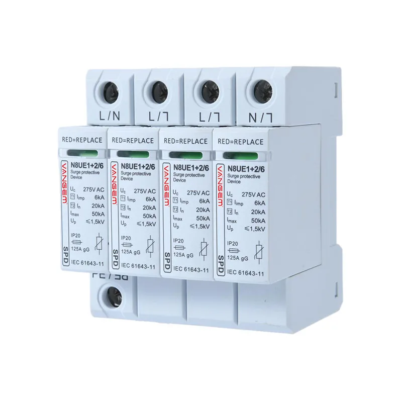
A useful final specification keeps the responsibilities separate: the drive controls the motor, the HVAC sequence defines the required mechanical output, and protection measures address their documented electrical functions. That separation lets buyers ask the correct supplier for the correct evidence without treating one component as a complete system solution.