
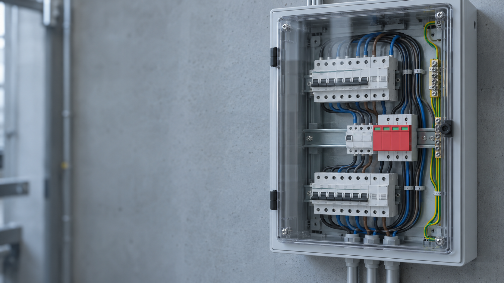
The N8UE2-40 surge protector wiring diagram below shows the original model-specific phase, neutral, PE and F1/F2 relationships published by Wanze. Use it to understand the depicted connection arrangements, then confirm the exact model instructions and electrical system before installation. Its terminal and fuse details are not universal for other SPDs.
The most reliable reading sequence is: identify the protected circuit, trace the current-carrying conductors, locate the SPD connection points, then verify the shortest practical path and the manufacturer’s required protection.
Published N8UE2-40 wiring diagram
The drawing below is the original connection sheet published on the N8UE2-40 product page. It provides a concrete reference for reading the phase, neutral, protective-earth and protective-device labels. Open the image at full size to inspect the lines.
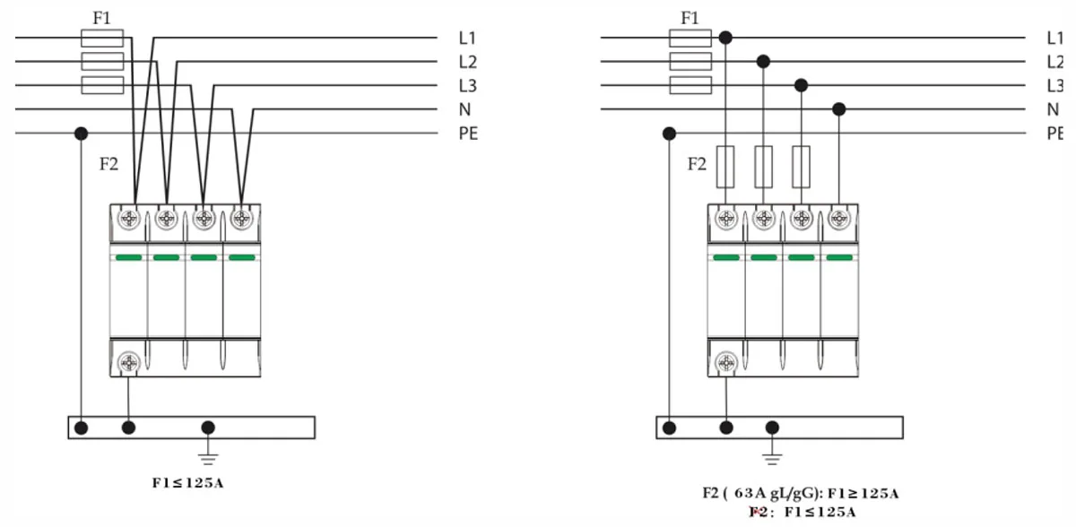
Read this sheet with the model’s technical data and current installation instructions. F1 and F2 identify protective-device positions in this drawing; their annotations must not be transferred to another model. A catalogue illustration is useful evidence of the published arrangement, but it does not resolve a different panel’s available fault current, protective-device coordination or local installation requirements.
Surge protector wiring diagram: what to identify
Most diagrams distinguish line or phase conductors, neutral when applicable, equipment grounding, an overcurrent device, the SPD enclosure, and the load or panel. A diagram can show the intended relationship without proving that a different voltage, topology, enclosure, or product family is compatible.
Schneider Electric explains why lead length matters: inductance in long or sharply bent conductors adds voltage during a fast surge. Treat the diagram’s routing guidance as part of the protection design. Do not redraw it from memory or substitute a generic color code for the actual manual.
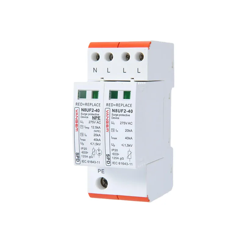
Diagram reading checklist
| Diagram element | Question | Evidence to confirm |
|---|---|---|
| Line or phase | Which conductors and modes are protected? | System topology and terminal markings in the manual. |
| Neutral or reference | Is a neutral or reference connection required? | Product wiring diagram and system one-line. |
| Ground path | Where does the SPD connect to the grounding or bonding system? | Qualified design and current installation instructions. |
| OCPD or disconnect | What protects or isolates the SPD branch? | Manufacturer limits, panel capacity, and project review. |
| Lead routing | Are conductors short, straight, and grouped as instructed? | Actual panel geometry and the manual’s routing guidance. |
Why conductor length deserves attention
Schneider’s guidance notes that every extra length of conductor adds inductive voltage during a transient. The practical instruction is to keep the connection as short and direct as possible, avoid unnecessary bends, and follow the exact product limits. Do not turn a rule of thumb from one device into a guaranteed value for another.
For product-family discovery, review the Wanze AC category. For installation, use the current model manual, local requirements, and a qualified electrical professional. This article intentionally does not provide a field wiring recipe.
Single-phase, three-phase and PV diagrams answer different questions
| System description | What the drawing must make explicit | What not to assume |
|---|---|---|
| Single-phase AC | Supply arrangement, neutral if used, protection modes and grounding connection. | That every two-wire supply has the same voltage reference or uses the same module arrangement. |
| Three-phase AC | Phase conductors, presence or absence of neutral, system grounding and the exact device configuration. | That adding another pole to a single-phase drawing creates an approved three-phase diagram. |
| PV DC | Positive and negative conductors, DC voltage basis, earth reference and a PV-rated device. | That AC terminal labels or AC protective-device instructions can be reused on the array side. |
A 120/240 V split-phase description and a 230 V line-neutral description are not interchangeable system specifications. Similarly, the phrase “three-phase” does not tell you whether a neutral is present. Obtain the actual one-line before trying to match a catalogue connection sheet.
The solar PV SPD range is a separate product path from the AC devices. An inverter can have both DC and AC connections, so “inverter surge protection” alone does not identify which diagram is required.
Why an SPD branch is different from the load circuit
Many power SPDs are connected as a parallel protection branch, rather than carrying the load current in series. The conceptual question is where the branch connects and which conductors or modes it protects. Do not read a parallel SPD symbol as an instruction to route the entire feeder through a small protective module.
Schneider Electric’s connection guidance explains the extra voltage associated with SPD leads during a fast transient. That is a different phenomenon from the steady-load conductor drop calculated in a normal feeder worksheet. A correct device rating therefore needs an appropriate physical connection path to be useful at the equipment.
Resolve these drawing mismatches before an installation review
- The drawing includes a neutral but the site description does not.
- The module label or suffix differs from the drawing title.
- The requested protective device is absent from the document, or a maximum backup-fuse value has been mistaken for a universal required fuse.
- The image is a product photograph without terminal relationships.
- The panel route, enclosure space or conductor limits cannot be established from the supplied information.
Use the SPD type comparison to check the classification context, then return to the exact model drawing. Keep location, ratings and terminal arrangement in the same review record.
FAQ
Can I use one generic SPD wiring diagram?
No. The topology, terminals, overcurrent arrangement, enclosure, and grounding context may differ. Start with the selected model’s current diagram.
Why should SPD leads be short?
Longer conductors add inductive voltage during a fast transient, reducing the protection available at the equipment terminals.
Does the diagram specify breaker size?
Only if the product documentation states it. Verify the manufacturer’s OCPD limits, conductor range, and panel constraints instead of guessing.